PLDC01938
REVISION 00
01/06/2011
TECHNICAL DEPT
Stavale
- date 05/09/2011
166/195
13
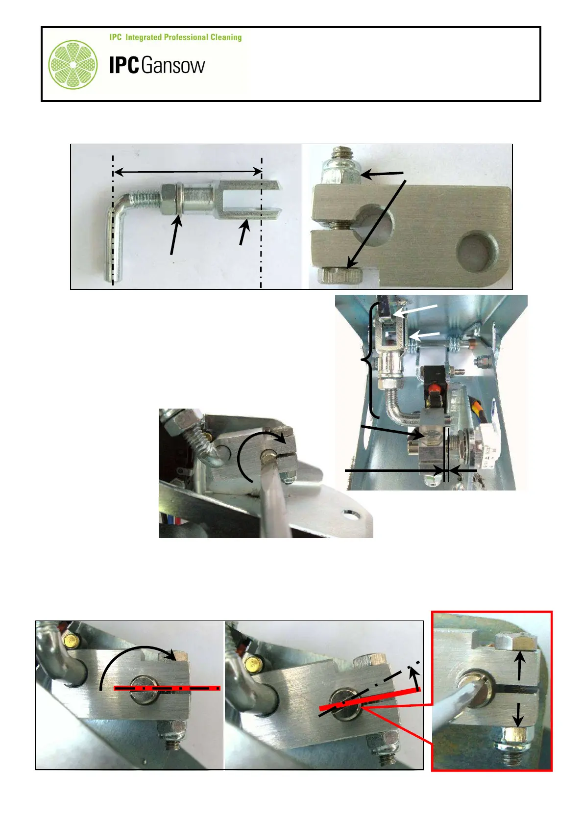
Check that the lever with fork A is 45 mm ± 1 mm long and that the axis of the fork is aligned with the axis of
the lever.
14
Proceed to mount the connecting rod D on the shaft of the potentiometer B.
15
Mount the lever with fork A on the pedal by first inserting
the lever into the hole in the connecting rod D, then
inserting the fork in the hole A4 in the top pedal. Mount the
clip A3 correctly.
16
Lightly tighten the bolt D1 on the shaft of the potentiometer
B to allow the shaft to rotate with slight interference in the
hole of the connecting rod D
17
Maintain a distance of a few millimetres from the body of
the potentiometer B, see photograph below.
18
With the pedal fully raised, use a screwdriver to turn the potentiometer to ZERO by rotating the shaft
clockwise as far as it will go.
19
Keeping the pedal fully raised, turn the shaft a few degrees anticlockwise away from the limit
position to avoid jeopardising the reliability of the potentiometer.
20
After adjusting the position, tighten the bolt D1 with a maximum torque of 3.0 Nm (~ 0.3 kgm ), to
block the position identified.
45 ± 1 mm
PHOTO 345
D1
D
PHOTO 347
D1
A3
A4
A
PHOTO 346
0°
PHOTO 348