PLDC01938
REVISION 00
01/06/2011
TECHNICAL DEPT.
Stavale
- date 05/09/2011
23/195
7
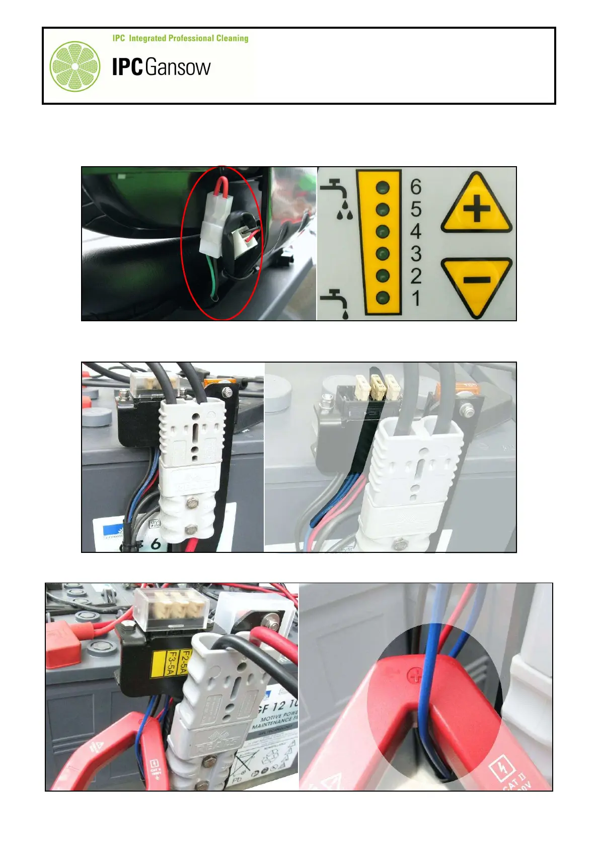
Disconnect the "operator present" sensor connector A and bridge it with a special connector.
8
Lift the tanks to facilitate access to the fuse holder.
9
Place the ignition key in position "1".
10
Press the button B to set water flow to zero, no LED on.
11
The fuse holder C is located alongside the Anderson plug D for recharging the batteries.
12
Identify the 5A head actuator fuse E with two blue wires.
13
Insert the jaws of the clamp meter between the two blue wires connected to the 5A actuator fuse E.
A
PHOTO 48
PHOTO 49
E
PHOTO 50
E