PLDC01938
REVISION 00
01/06/2011
TECHNICAL DEPT.
Stavale
- date 05/09/2011
24/195
14
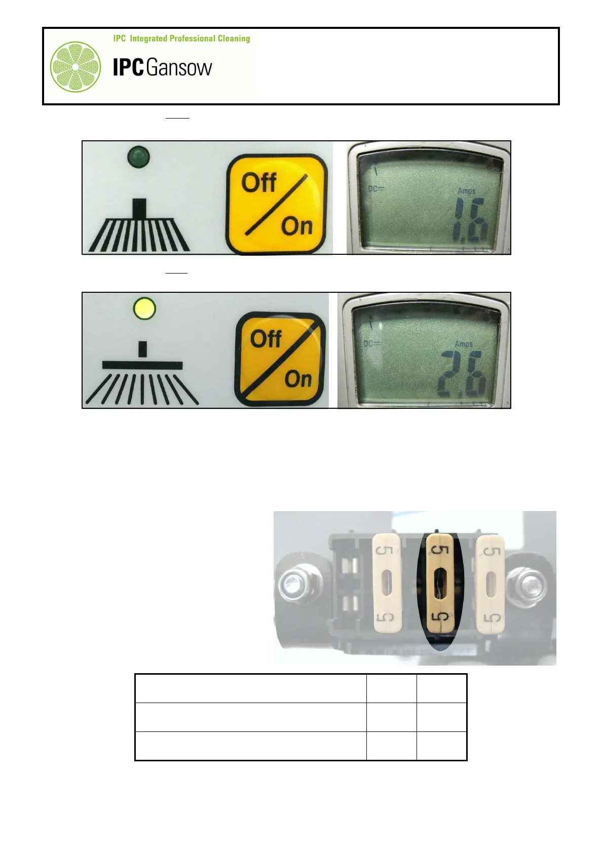
Press the button F to lower the brush head.
15
Read the draw in amps and compare with the table below.
16
Press the button F to raise the brush head.
17
Read the draw in amps and compare with the table below.
18
If the values are within the range shown in the table below, everything is within the norm. Disconnect the
clamp meter and replace the tanks in position.
19
If the measurements do not correspond to those specified but are higher:
19a
Check that the head parallelogram is free to move up and down without interference and that there are no
squeaks or rubbing sounds.
19b
Check the draw of the actuator without load (detached from the head) or replace the actuator with a new
one.
The circuit board controls the head
actuator during raising and lowering,
powering it through the MOS-FET with
an ON-OFF command (switch type).
If current draw is high or there is a short
circuit, the 5A fuse trips and current to
the actuator is shut off.
Draw A (amps) Min Max
During lowering 0.8 A 3.0 A
During raising 1.2 A 3.0 A
PHOTO 51
F
i