PLDC01938
REVISION 00
01/06/2011
TECHNICAL DEPT.
Stavale
- date 05/09/2011
30/195
20
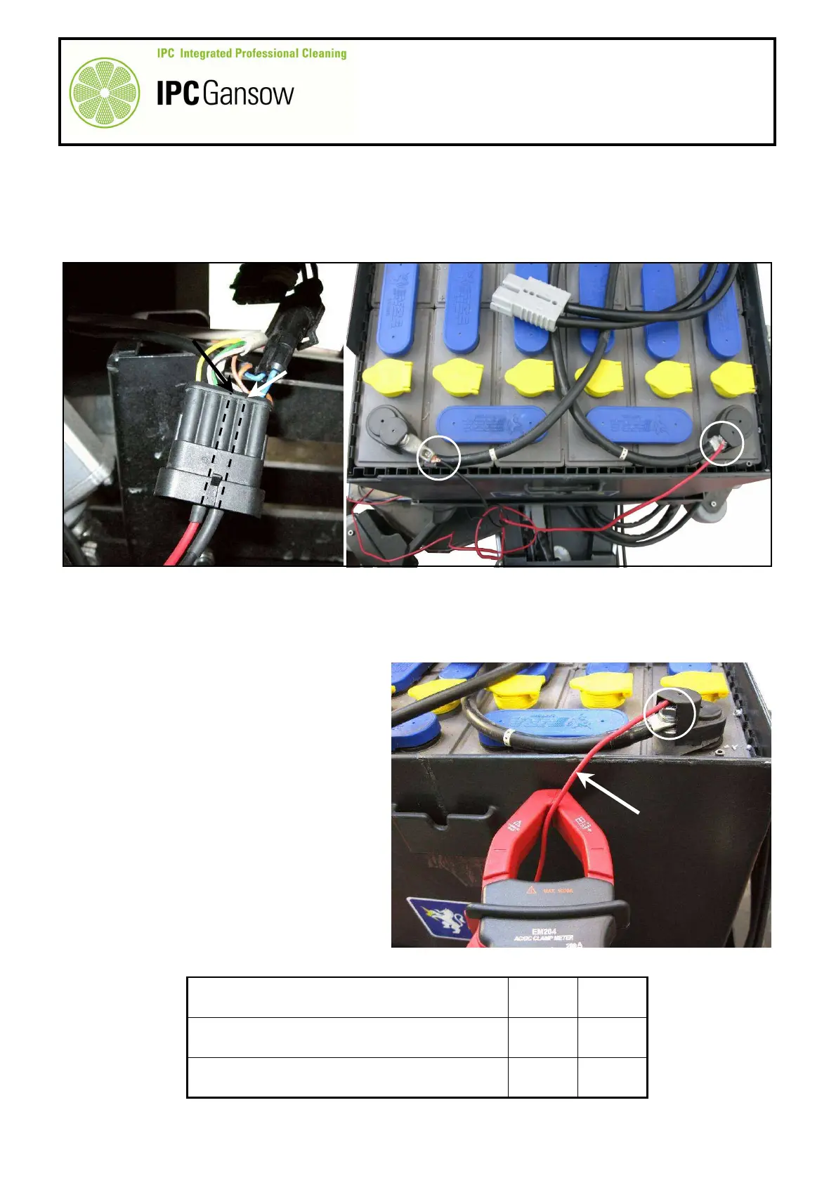
Connect the two wires A1 - A2 to the connector B, connecting the terminal of the red wire A1 to the plug of
the white wire B3 in position 3 of the connector B and the terminal of the black wire A2 to the plug of the
grey and brown wires B2 in position 2 of the connector B.
21
Connect the other end of the red wire A1 to the positive pole F of the battery and the other end of the black
wire A2 to the negative pole G.
22
If the actuator raises the head to the maximum height (without problems such as a burnt out fuse H), this
means that it is working correctly and the cause of possible malfunctions must be sought elsewhere (wiring,
control panel board).
23
Check the actuator absorption value in any case, by measuring the signal from the wires A1 or A2 used for
the connection or from the fuse box as
described in paragraph A2.1.
24
If on the other hand the actuator does not
move, remove it, take it to the bench and test
the internal micro switches, see paragraph
A2.4.
25
If it starts to move then stops because the
fuse H has burnt out, it could mean that the
current draw of the actuator when it tries to
raise the head is high. Remove the actuator
and test both operation and current draw
without load on the bench.
26
Check that the head levers are not resisting
movement due to friction or interference.
27
Compare the draw values read with those
given in the table below.
Draw A (amps) Min Max
During lowering 1.2 A 3.0 A
During raising 0.8 A 3.0 A
PHOTO 65
B2
A2
A1
A2
A1
G
F
B
D
B3
PHOTO 66
F
A1