PLDC01938
REVISION 00
01/06/2011
TECHNICAL DEPT.
Stavale
- date 05/09/2011
41/195
37
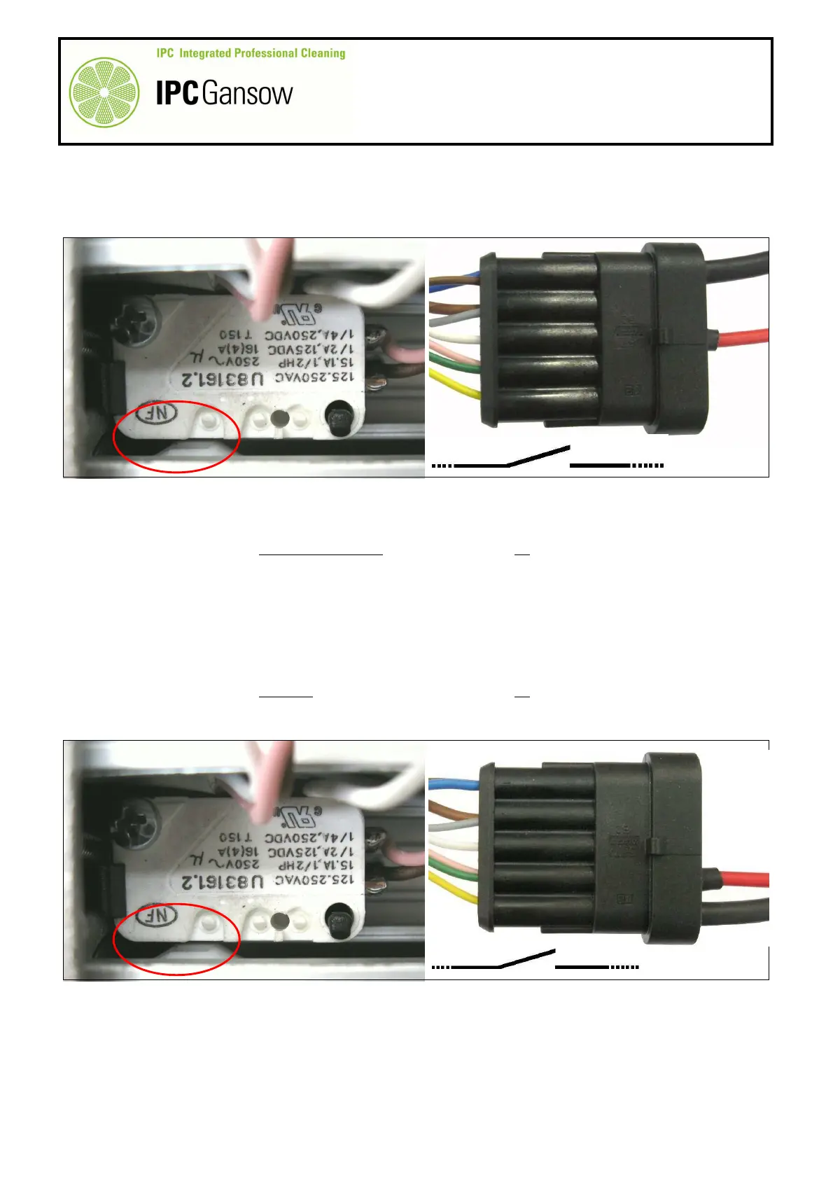
Move the black wire E2 from position 4 to position 1 of the connector B and connect to the terminal of the
brown wire B1.
38
Connect the opposite ends of the wires E1 and E2 to the digital multimeter again and check electrical
continuity.
39
In this situation, continuity must not be present and there should be no movement of the digital multimeter
display.
40
Keep the cam K of the rod A1 in the same position and with the actuator button X1 of micro switch X
pressed, check operation of the micro switch Y.
41
Connect the plug on the red wire E1 to the terminal of the green-pink wires B4, position 4 of the connector B.
42
Connect the plug on the black wire E2 to the terminal of the yellow wire B5, position 5 of the connector B.
43
Connect the opposite ends of the wires E1 and E2 to the digital multimeter and check electrical continuity.
44
In this situation, continuity must not be present and there should be no movement of the digital multimeter
display.
45
Now check the grey wire B2, connecting the plug of wire E1 to the terminal of the grey wire B2, position 2 of
the connector B.
46
Connect the opposite ends of the wires E1 and E2 to the digital multimeter and check electrical continuity.
X
PHOTO 92
E1
E2
4 5
B
NO
PHOTO 91
E1
1 3 4
B
B1
K
X
NO
E2