PLDC01938
REVISION 00
01/06/2011
TECHNICAL DEPT.
Stavale
- date 05/09/2011
42/195
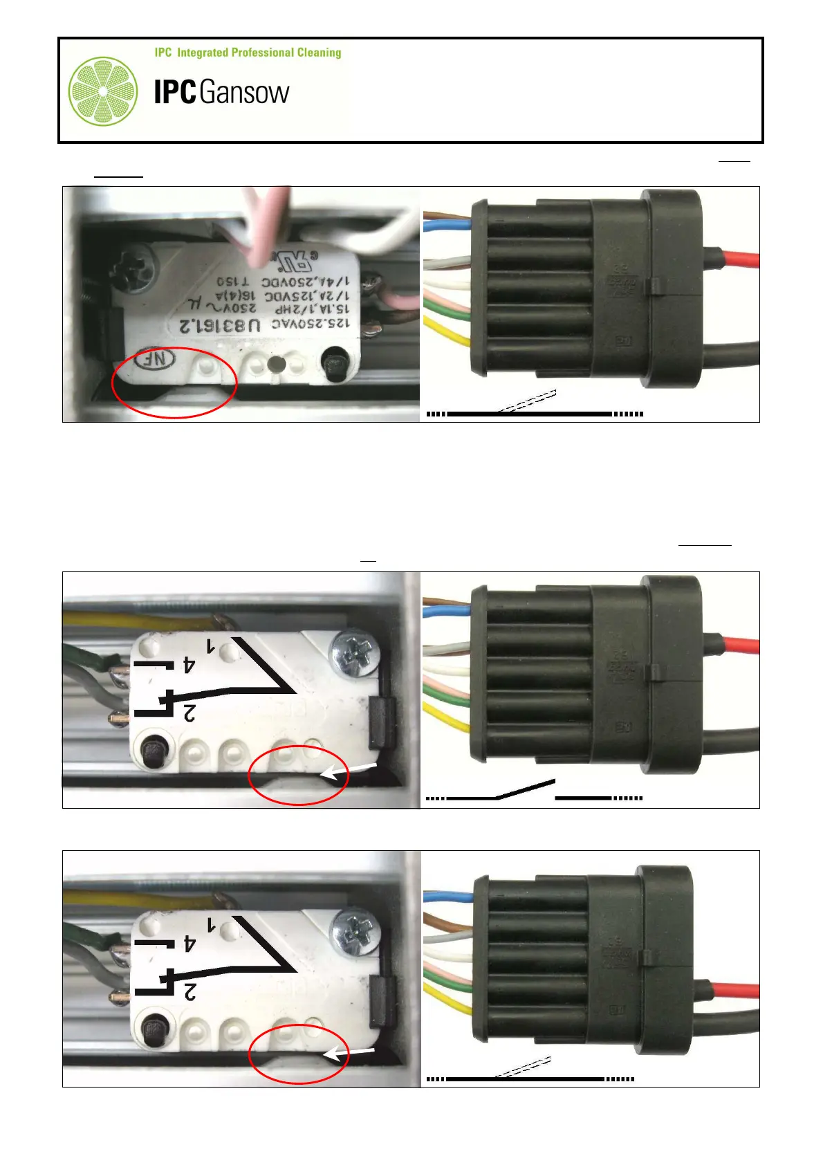
47
As the actuator button Y1 (of the micro switch Y) is in the inactive position, thus normally closed (NC), there
must be continuity and there will be movement on the digital multimeter display.
48
By manually unscrewing the rod A1 completely, move the position of cam K until the actuator button Y1 of
the micro switch Y is pressed.
49
Continue checking the grey wire B2, keeping the plug on the wire E1 on the terminal of the grey wire B2,
position 2 of the connector B, and the plug on the wire E2 on the terminal of the yellow wire B5, position 5 of
the connector B.
50
Connect the opposite ends of the wires E1 and E2 to the digital multimeter and check electrical continuity.
51
The micro switch Y is no longer in the NC inactive position, breaking electrical continuity. There must not
therefore be continuity and there should be no variations on the digital multimeter display.
52
Move the red wire E1 from position 2 to position 4 of the connector B and connect to the terminal of the
green-pink wires B4.
X
PHOTO 93
E1
E2
2 5
B
OK
K
PHOTO 94
E1
E2
2 5
B
K
E1
E2
2 4 5
B
OK
PHOTO 95