PLDC01938
REVISION 00
01/06/2011
TECHNICAL DEPT.
Stavale
- date 05/09/2011
43/195
53
Keep the cam K of the rod A1 in the same position and with the actuator button Y1 of micro switch Y
pressed, check operation of the micro switch X
54
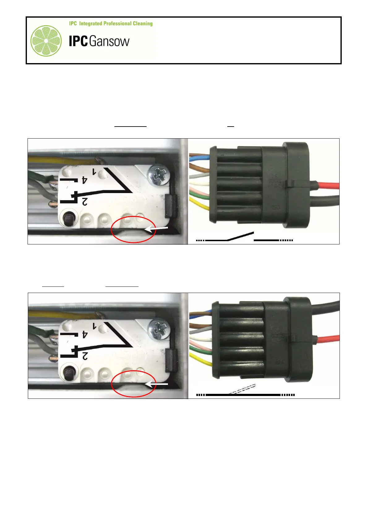
Connect the plug on the red wire E1 to the terminal of the white wire B3, position 3 of the connector B.
55
Connect the plug on the black wire E2 to the terminal of the green-pink wires B4, position 4 of the connector
B.
56
Connect the opposite ends of the wires E1 and E2 to the digital multimeter and check electrical continuity.
57
In this situation, continuity must not be present and there should be no movement of the digital multimeter
display.
58
Finally, check the brown wire.
59
Move the black wire E2 from position 4 to position 1 of the connector B and connect to the terminal of the
brown wire B1.
60
As the actuator button X1 (of the micro switch X) is in the inactive position, thus normally closed (NC), there
must be continuity and there will be movement on the digital multimeter display.
Result
61
If even one of the two micro switches X or Y is not functioning correctly, the actuator will malfunction. If
possible, replace the faulty micro switch or the complete actuator.
62
If the micro switches are functioning correctly, check the machine wiring relative to the actuator.
K
PHOTO 96
E1
E2
B
3 4
NO
E1
E2
PHOTO 97
1 3 4
B
B1
OK
K