PLDC01938
REVISION 00
01/06/2011
TECHNICAL DEPT.
Stavale
- date 05/09/2011
50/195
12
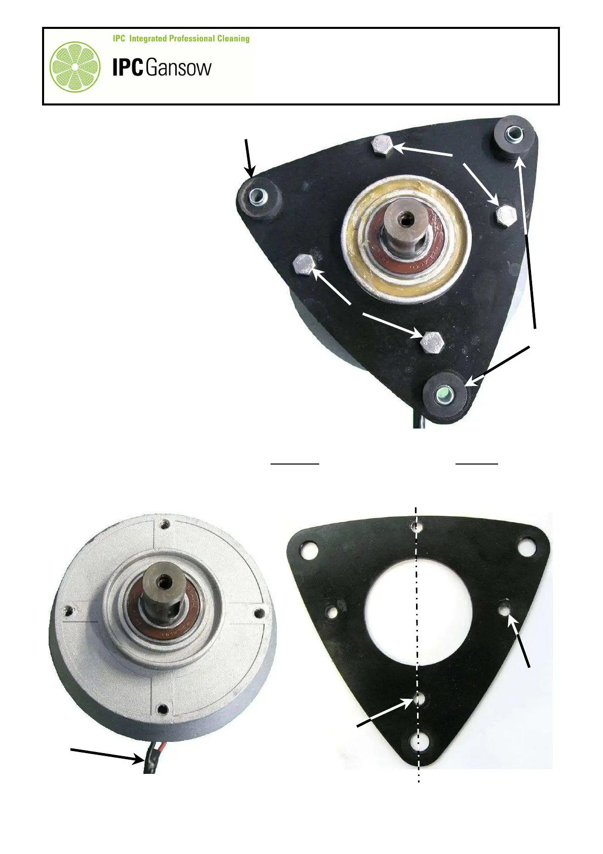
Remove the vibration dampers G
from the brush motor flange H.
13
Unscrew the four screws I fixing
the motor flange H to the brush
motor L.
14
Replace the motor L with a new
one with the same
characteristics.
15
Clean the flange H to remove dirt
and traces of thread lock.
16
Use hole H1 as a reference for mounting the right motor and hole H2 for mounting the left motor. The hole
H1 is recognisable as it is the only one with the same axis as the hole for the vibration dampers G.
H2
H1
PHOTO 114
H
L
PHOTO 113
L1
PHOTO 112
G
G
H
I
I