PLDC01938
REVISION 00
01/06/2011
TECHNICAL DEPT.
Stavale
- date 05/09/2011
71/195
7
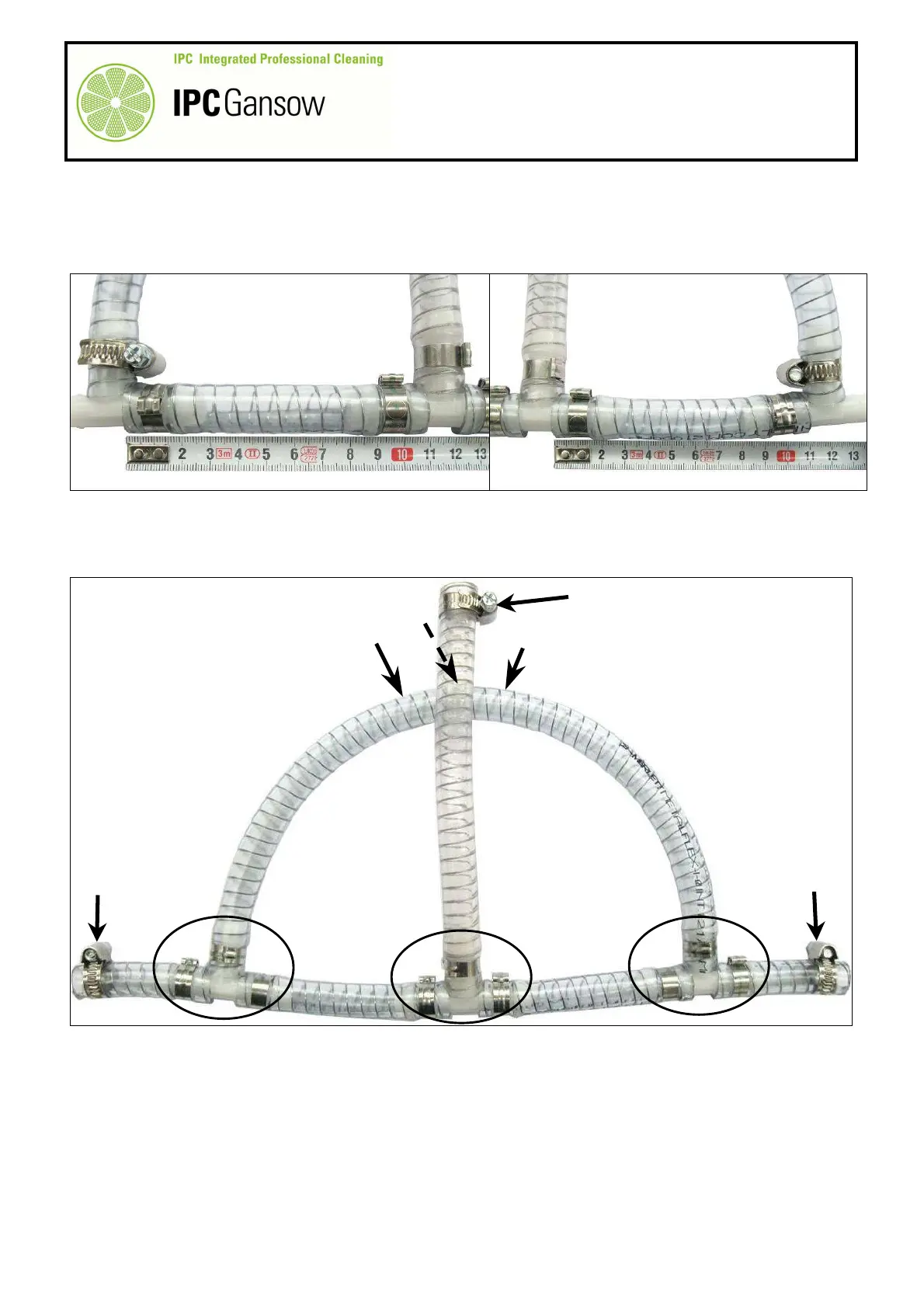
Obtain two pieces of hose C and D with a length of ~ 11 cm and the same diameter as the previous pieces
of hose (A - B).
8
To complete the hydraulic compensator, assemble the two hoses C and D to the tube B coming from the
solenoid valve and to the compensator hose A.
9
When curving the tube A, make sure the hose is positioned with the three holes A1 facing upwards.
10
To complete the compensation system, add a further two pieces of hose E and F which will be connected to
the hoses fastened to the head. Their length will depend on the size of the head (85 - 105).
Replacing
1
To replace or control the compensator, remove it from the solenoid valve and head hoses by unscrewing the
metal hose clips B2 - E1 - F1.
2
To replace the other tubes, remove the rapid clips G using pincers.
C
A
B A
B
PHOTO 159
A1
A1
A1
A
PHOTO 160
B
D
C
F
E
G
E1
F1
B2