Aircraft Technical Manual
J120, J160, J170, J200/J400, J230/J430, J250/J450 Variants
This document is controlled while it remains on the Jabiru server. Once this no longer applies the document becomes uncontrolled.
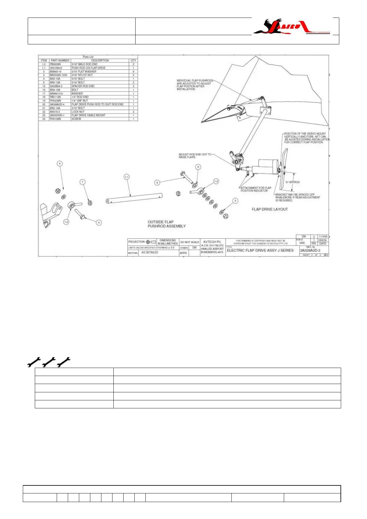
Figure 113 – J200 Family Electric Flap System Sheet 2 (J200/J400, J230/J430, J250/J450)
6.58 FLAP Cross SHAFT ASSEMBLY (all J-Series)
6.58.1 Description
As shown above the flaps are driven via a shaft which runs from one side of the fuselage to the
other.
In turn this shaft is an assembly of 2 different sized steel tubes with input and output arms attached.
6.58.2 Flap Cross Shaft Removal
Tools as required in Section 0
L2 or LAME (A&P or LSA Repairman / Maintenance)
L2 or LAME (A&P or LSA Repairman / Maintenance)
1. Remove one wing to allow removal of shaft. Refer to Section 0 for details on wing removal
procedure.
2. Either use heavy duty tape to hold the remaining flap in the up position or remove the flap
from the aircraft.
3. Disconnect the flap drive motor or manual lever from the cross shaft input arm.
4. Remove external flap drive arm from the end of the shaft nearest the remaining wing.