Aircraft Technical Manual
J120, J160, J170, J200/J400, J230/J430, J250/J450 Variants
This document is controlled while it remains on the Jabiru server. Once this no longer applies the document becomes uncontrolled.
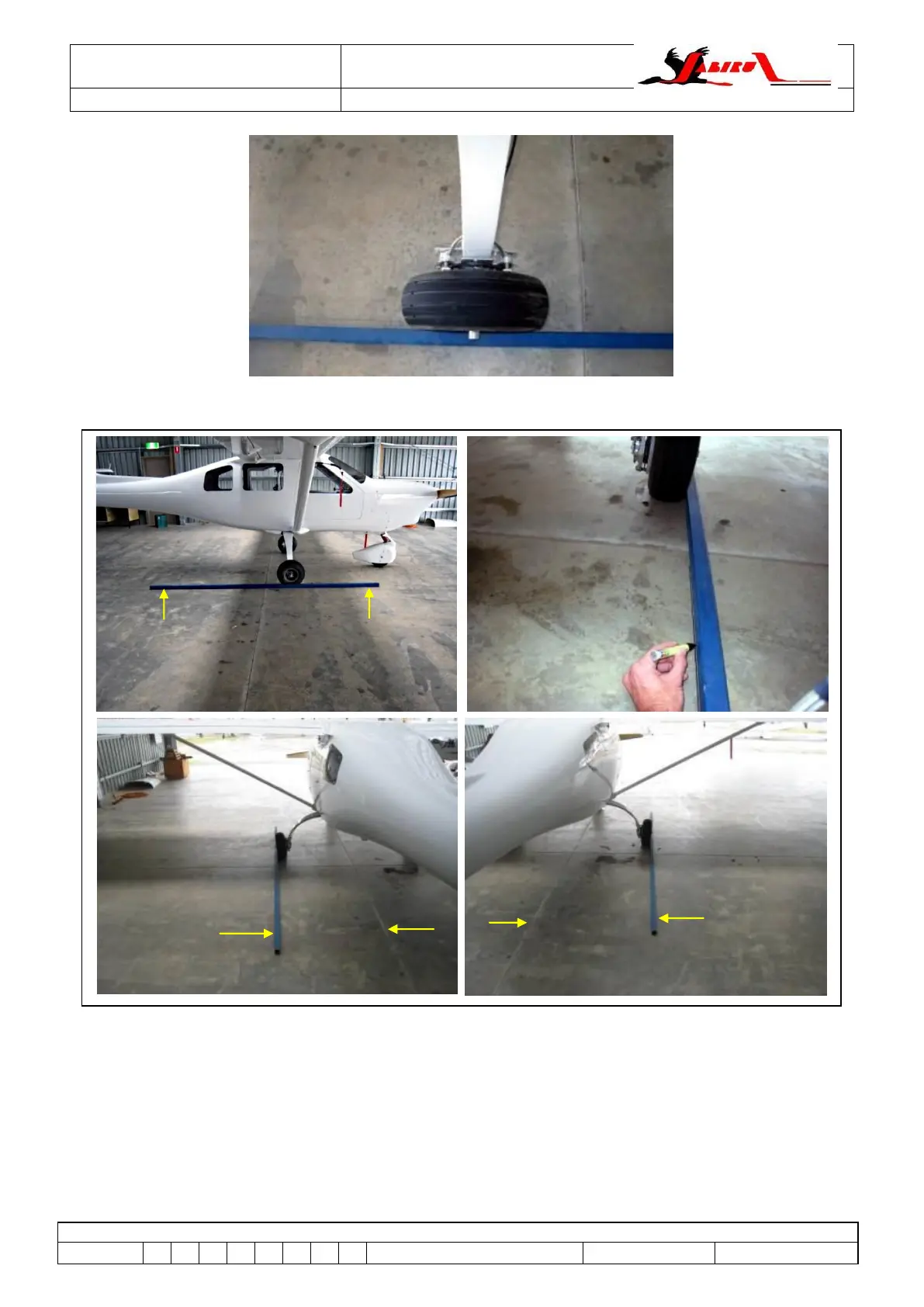
Figure 24 – Alignment Straight Edge In Position (all J-Series)
Figure 25 – Alignment Measurements (all J-Series)
Mark the position of the straight edge in front and behind the wheels. Positions are marked at 1.5m
nominally either side of the wheel centre.
Take measurements from the straight edge positions to the centreline of the fuselage.
Compare the measured distances to see if the wheels have toe-in or toe-out.
Camber is the vertical angle of the wheel to the ground. It is to be measured (using a digital
protractor or similar) using the end of the axle or the brake disk as a reference. The aim is to have
the wheel vertical when the aircraft is fully loaded.
Toe in / toe out and the wheel camber angle are related in that when the wheel has camber it
behaves like a cone and wants to track in a circle around the point where the centreline of the axle