Aircraft Technical Manual
J120, J160, J170, J200/J400, J230/J430, J250/J450 Variants
This document is controlled while it remains on the Jabiru server. Once this no longer applies the document becomes uncontrolled.
Figure 134 – Adjustable Rudder Pedal Assy – Type 1 (all J-Series)
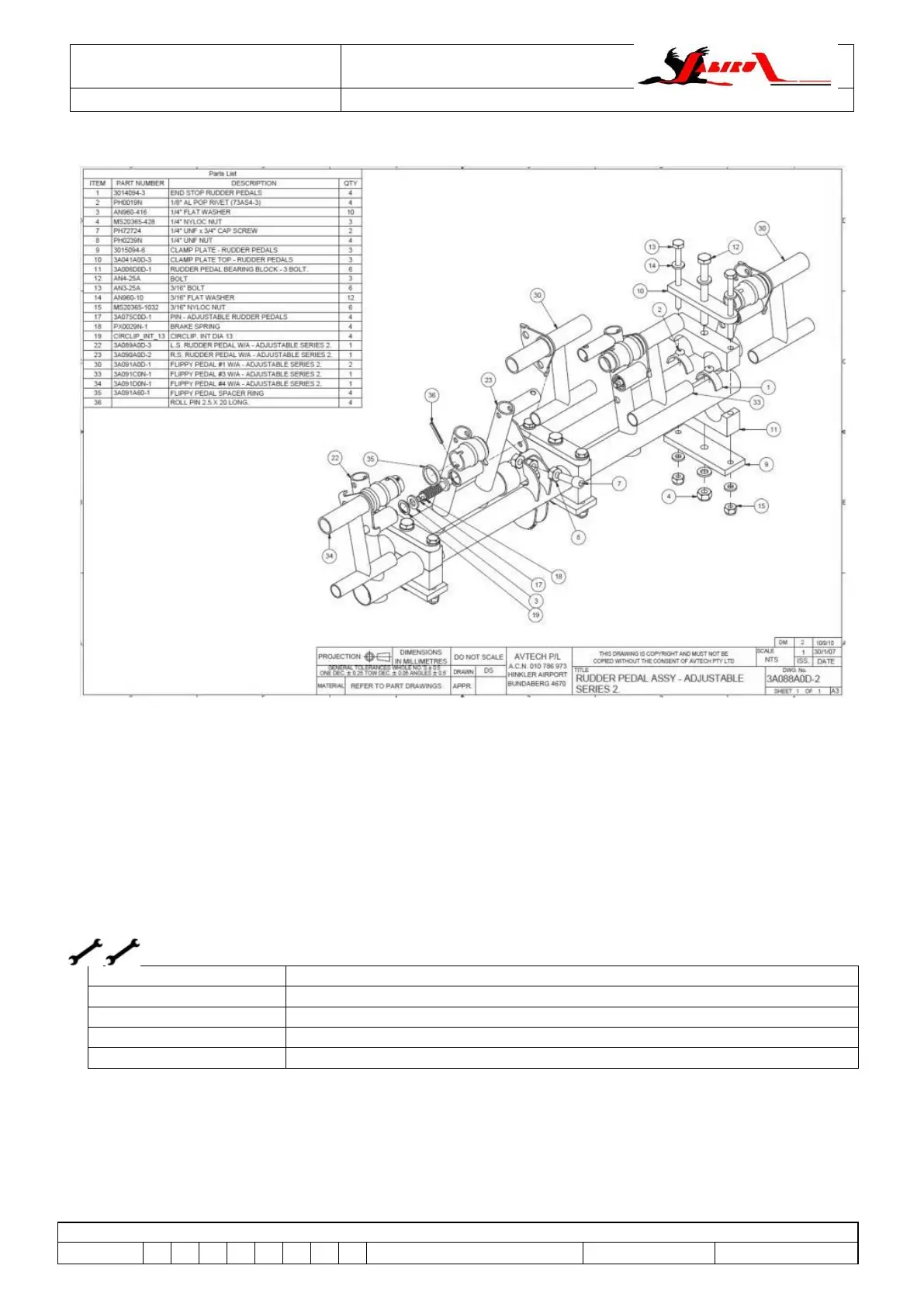
Figure 135 – Adjustable Rudder Pedal Assy – Type 2 (all J-Series)
6.72 Rudder Centring System (all J-Series)
6.72.1 Description
In Jabiru Aircraft the rudder pedals are connected directly to the nose leg. This gives both nose
wheel steering and the mechanism connecting the left and right pedals.
The drawings shown in Figure 136 through to Figure 140 show several variations of the systems
used.
6.72.2 Rudder Centring System Removal
L1, L2 or LAME (Owner, A&P or LSA Repairman / Maintenance)
L1, L2 or LAME (Owner, A&P or LSA Repairman / Maintenance)
For details on removing the nose leg and rudder pedals refer to the appropriate sections of this
manual.
To disconnect the rudder centring system, remove the bolts and the pushrods connecting the pedals
to the nose leg or centring bellcrank.