Aircraft Technical Manual
J120, J160, J170, J200/J400, J230/J430, J250/J450 Variants
This document is controlled while it remains on the Jabiru server. Once this no longer applies the document becomes uncontrolled.
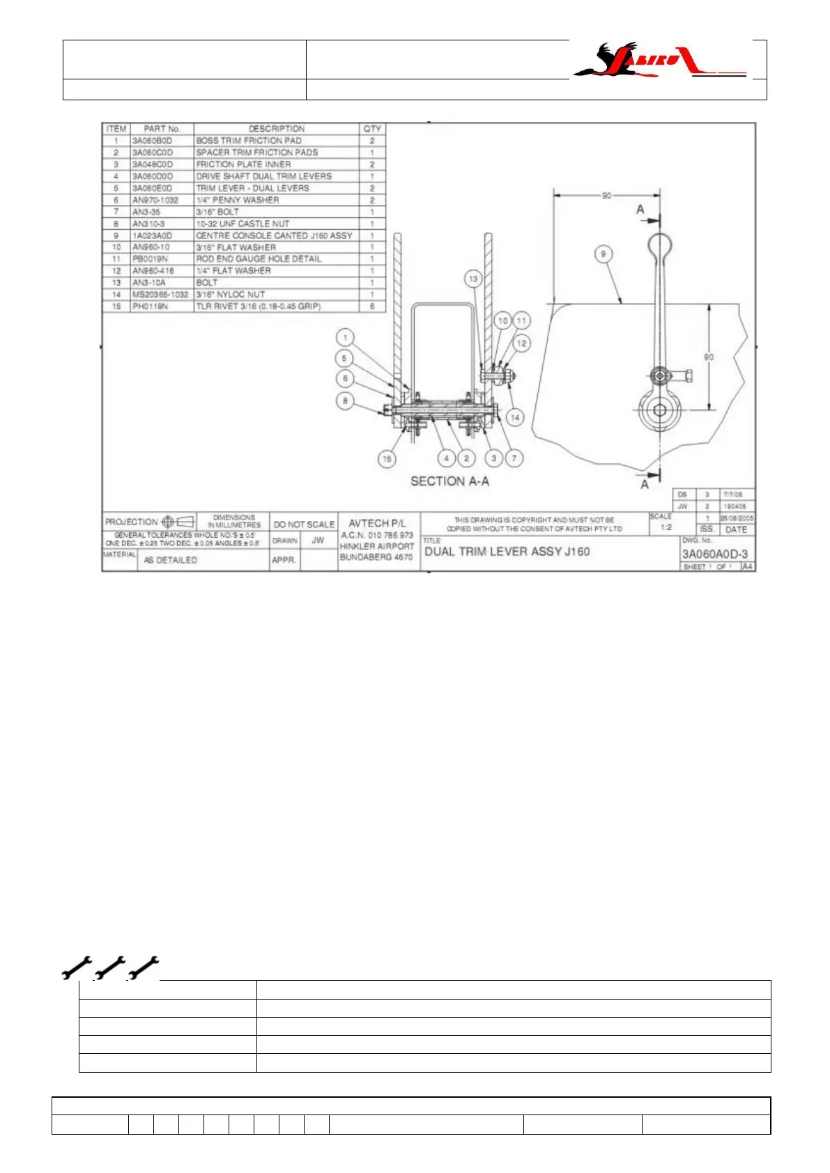
Figure 130 – Elevator Trim Handle Assy – Type 3 (all J-Series, n/a J200/J400)
6.69 Elevator Trim – Aft Assembly (all J-Series)
6.69.1 Description
The elevator trim control system comprises a Trim Cable connected to a lubron block, so that the
cable is able to move the block fore and aft approximately 35mm. An aluminium rod is free to slide
through this lubron block and is centred by 2 compression springs. The output end of the rod is
connected to the Elevator Horn.
This assembly allows a spring-loaded connection between the elevator trim lever and the elevator.
This spring loading force is used to trim the aircraft.
6.69.2 Operational Check
Movement of the Trim Lever FORE and AFT should result in movement of the Main Control FORE
and AFT and movement of the Elevator UP and DOWN.
WARNING
It is important to carry out this operational check whenever the trim cable has been disconnected
to ensure it has been correctly installed.
6.69.3 Removal
L1, L2 or LAME (Owner, A&P or LSA Repairman / Maintenance)
L1, L2 or LAME (Owner, A&P or LSA Repairman / Maintenance)