Aircraft Technical Manual
J120, J160, J170, J200/J400, J230/J430, J250/J450 Variants
This document is controlled while it remains on the Jabiru server. Once this no longer applies the document becomes uncontrolled.
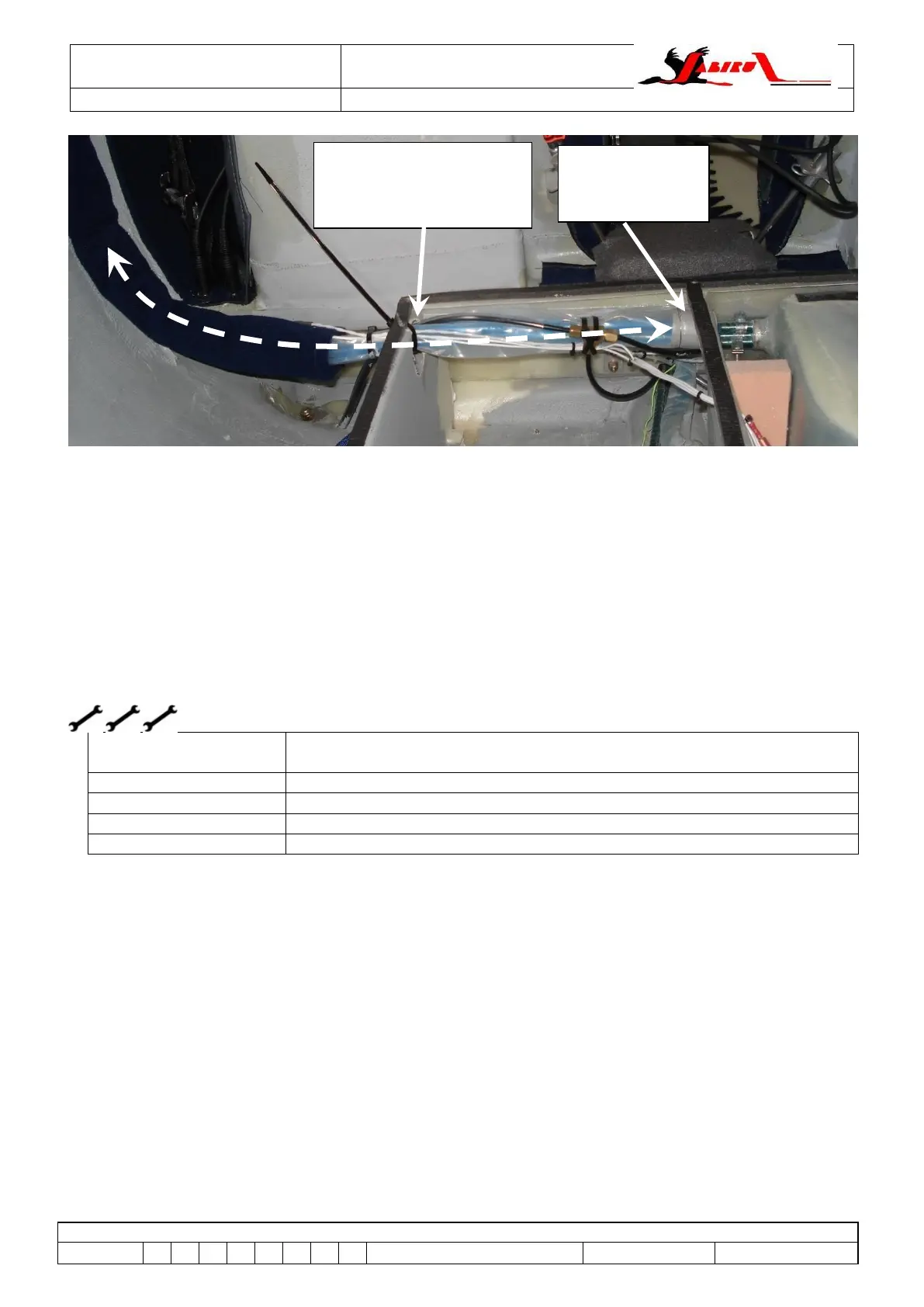
Figure 171 – Corrected Fuel Lines (all J-Series)
8.3 Fuel Tanks (all J-Series)
8.3.1 Description
Where wing tanks are fitted, the composite tanks are located in the left & right hand wings. A header
tank is also fitted – either under the passenger’s seat, under the baggage shelf or behind the rear
sound curtain. Wing tanks are an integral part of the wing structure whereas header tanks are non-
structural and may be removed if required.
A sump drain plug is provided for each tank.
8.3.2 Fuel Tank Removal
Spanners / Socket Wrench
Screwdrivers
L2 or LAME (A&P or LSA Repairman / Maintenance)
L2 or LAME (A&P or LSA Repairman / Maintenance)
As the wing fuel tanks are part of the wing integrity, these fuel tanks cannot be removed.
The header tanks may be removed if necessary to check outlet strainers etc.
- Drain fuel from wing tanks.
- Remove the drain plug and drain the fuel from the header tank.
- Remove the cover from the header tank enclosure. For kit-built models where the tank is under
the passenger’s seat this may require cutting a hole into the seat pan.
- Remove tank restraints.
- Loosen hose clamps, remove hoses & remove tank.
- Installation is the reverse of removal.
Main fuel tanks installed in the cabin can be removed:
- Drain the tank.
- Loosen the tank restraining straps
- Loosen and remove the filler hose between the tank and the fuel filler on the outer skin of the
fuselage.
- Disconnect the earth wire between the tank and the fuel filler earth point.
- Lean the tank to one side to allow access to disconnect the fuel line.
Hole in baggage shelf
wall raised, zip-tie used
to hold line bundle up.
Outlet from tank
enclosure raised
slightly