CUTTING UNITS
4222983 Second Edition 6-29
6
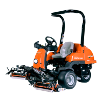
Figure 6-32
5. Remove screws (2) and lock washers (3).
6. Remove counterweight (1).
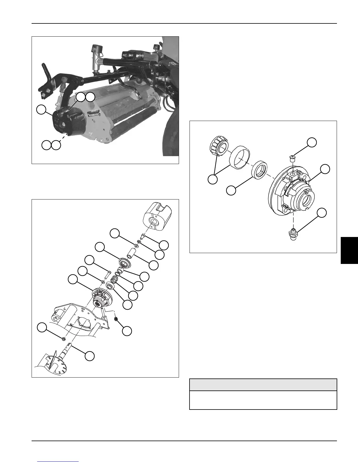
Figure 6-33
7. Remove grease fitting (11).
8. Remove screw (4), lock washer (5), flat washer (18),
and spacer (6).
9. Remove four screws (16), washers (15), and nuts
(13).
10. Remove seal (17).
11. Remove nut (7).
12. Remove washer (8) and spring (9).
13. Remove reel bearing housing assembly (14) using
reel bearing housing puller (Jacobsen PN JAC5085).
14. Inspect reel shaft (12) for wear or damage. Replace
reel if needed. (See “Reel Assembly” on page 6-30.)
Disassembly and Assembly
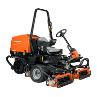
See Figure 6-34.
Figure 6-34
Assembly Notes
• Install new grease seal (2).
• Inspect bearing cup and cone (1) for wear or
damage. Replace as needed.
• Pack bearing (1) with grease that meets or exceeds
NLGI Grade 2 LB specifications before assembly.
• Apply grease that meets or exceeds NLGI Grade 2
LB specifications to the lips of the grease seal (2).
Installation—Non-Drive Side
See Figures 6-35 and 6-36.
TN2650
1
2 3
2 3
TN1699
6
7
8
9
4
5
10
12
13
14
15
16
17
18
11
1 Bearing Cup and Cone 4 Reel Bearing Housing
2 Grease Seal 5 Grease Fitting
3 Vent Fitting
Required Tools or Equipment
Bearing Assembly Tool
(Jacobsen PN JAC5084)
TN0940
5
4
1
2
3
 Loading...