GENSET AND BATTERY PACK
4222983 Second Edition 3-23
3
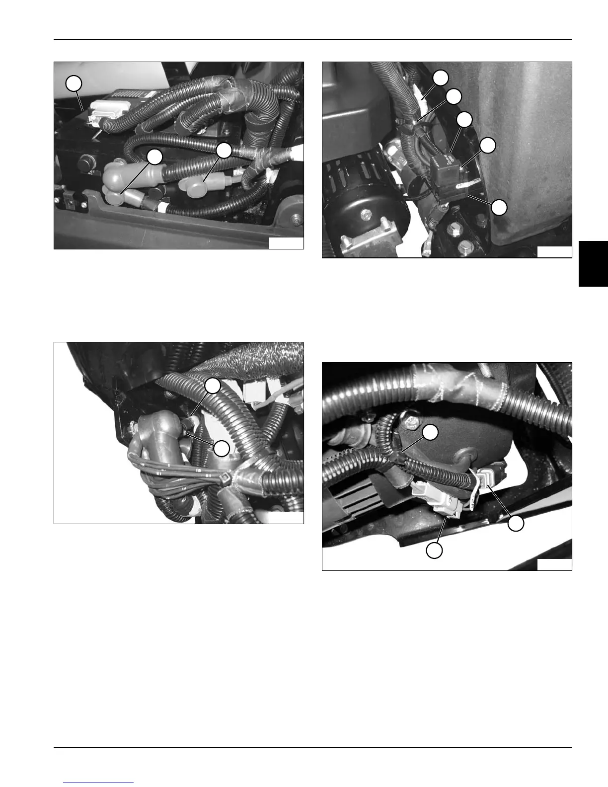
Figure 3-35
12. Tag and disconnect the generator positive (+) output
cable (6) and 12 VOLT POS connector (7) from PDU
(5). Carefully guide the cables away from the PDU
and position the cables to be unrestricted during
genset removal.
Figure 3-36
13. Tag and disconnect the generator negative (–) output
cable (8) from ground stud (9). Carefully guide the
cable away from the frame and position the cable to
be unrestricted during genset removal.
Figure 3-37
14. Tag and disconnect rectifier connector (10).
15. Cut cable tie (11).
16. Remove fan relay (12).
17. Remove screw (13) and fan relay base (14).
18. Remove GCU. (See “GCU” on page 4-144.)
Figure 3-38
19. Tag and disconnect genset connector (17) and
genset fan connector (16).
20. Cut cable tie (15).
21. Move the wiring harness away from the genset.
TN2712
7
6
5
TN2714
8
9
TN2713
13
12
10
14
11
TN2754
17
15
16