Powered by Eaton Technology VSD Series Drives User Manual
LIT-1201828
For more information visit: www.johnsoncontrols.com 10-7
November 2009
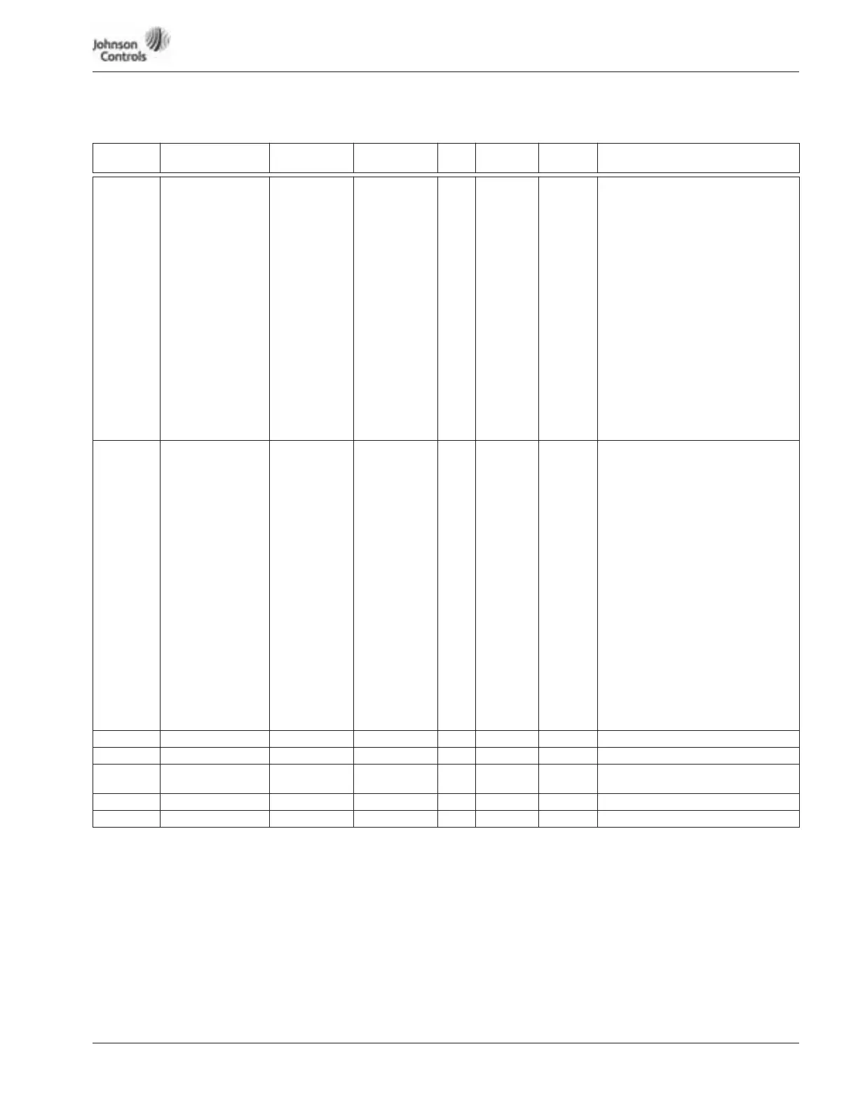
Table 10-3: Input Signals — M1 ➔ G1.2, continued
Code Parameter Min. Max. Unit Default
ID
Number Description
P1.2.8 (A) DI-5 Funct. 0 17 9 207 Default #9 Fire-Mode
0 = Not Used
1 = Ext. fault, closing contact
2 = External fault, opening contact
3 = Fault reset
4 = Run enable-Closed Contact
5 = Force ctrl. place to Hand
6 = Force ctrl. place to Auto
7 = Reverse
8 = Speed Select 1
9 = Fire Mode-Closed Contact
10 = Speed Select 2
11 = Speed Select 3
12 = Force Bypass
13 = External interlock closed
14 = External interlock open
15 = Mot. Pot. UP
16 = Mot. Pot. DOWN
17 = Fire Mode-Open Contact
P1.2.9 (A) DI-6 Funct. 0 17 0 208 Default #0 Overload Fault
Relay-input
0 = Overload fault relay (Used in
Intellipass)
1 = Ext. fault, closing contact
2 = External fault, opening contact
3 = Fault reset
4 = Run enable-Closed Contact
5 = Force ctrl. place to Hand
6 = Force ctrl. place to Auto
7 = Reverse
8 = Speed Select 1
9 = Fire Mode-Closed Contact
10 = Speed Select 2
11 = Speed Select 3
12 = Force Bypass
13 = External interlock closed
14 = External interlock open
15 = Mot. Pot. UP
16 = Mot. Pot. DOWN
17 = Fire Mode-Open Contact
P1.2.10
(A) AI-1 Minimum
0.00 Max. % 0.00 217 Default applies for 0V or 0 mA
P1.2.11
(A) AI-1 Maximum
Min. 100.0 % 100.00 218 Default applies for 10V or 20 mA
P1.2.12 (A) AI-1 Invert 0 1 0 209 0 = Not inverted
1 = Inverted
P1.2.13 (A) AI-1 Filter 0.00 10.00 s 0.10 210 0 = No filtering
P1.2.14
(A) AI-2 Minimum
0.00 Max. % 20.00 219 Default applies for 2V or 4 mA