Powered by Eaton Technology VSD Series Drives User Manual
LIT-1201828
For more information visit: www.johnsoncontrols.com 15-9
November 2009
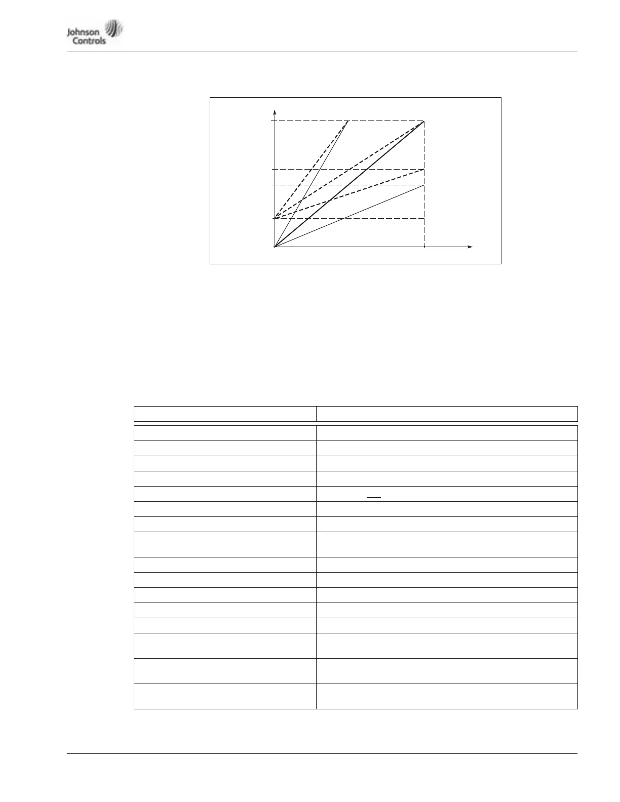
Figure 15-9: Analog Output Scaling
306 Digital output function
307 Relay output 1 function (B)
308 Relay output 2 function (B)
309 Relay output 1 function (D)
310 Relay output 2 function (D)
311 Relay output 3 function (D)
Table 15-3: Output Signals Via DO-1 and Output Relays RO-1 and RO-2
Setting value Signal content
0 = Not used Out of operation
1 = Ready The drive is ready to operate
2 = Run The drive is operating (motor is running)
3 = Fault A fault trip has occurred
4 = Fault inverted A fault trip not
occurred
5 = Overheat warning The heat-sink temperature exceeds +70°C/+158°F
6 = External fault or warning Fault or warning depending on ID703
7 = Reference fault or warning Fault or warning depending on par. ID702
• if analog reference is 4 – 20 mA and signal is <4 mA
8 = Warning Always if a warning exists
9 = Reversed The reverse command has been selected
10 = Preset Speed Active Preset Speed Active digital input
11 = At speed The output frequency has reached the set reference
12 = Motor regulator activated Overvoltage or overcurrent regulator was activated
13 = Output frequency limit supervision The output frequency is outside the set supervision low
limit/high limit (ID314 and ID315)
14 = Speed setpoint limit supervision The output frequency goes outside the set supervision low
limit/high limit (ID312 and ID313)
15 = Torque limit supervision The motor torque is beyond the set supervision low limit/
high limit (ID316 and ID317).
Analog Output
Current
20 mA
12 mA
10 mA
ID304 = 1
4 mA
ID304 = 0
0 mA
0 0.5 1.0
Scale =
50%
Max. Value
of Signal
Selected
by ID301
Scale = 200%
Scale =
100%