VSD Series Drives User Manual Powered by Eaton Technology
12-8 For more information visit: www.johnsoncontrols.com LIT-1201828
November 2009
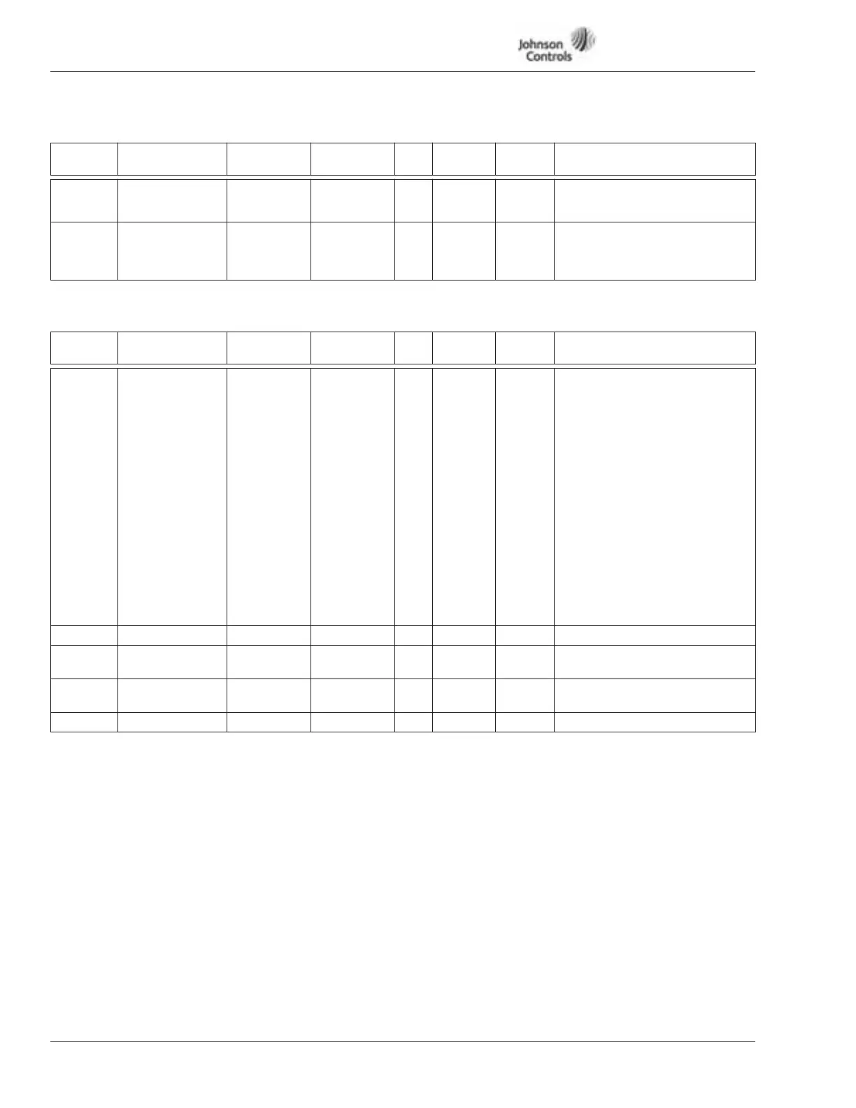
Table 12-3: Input Signals — M1 ➔ G1.2, continued
Output Signals — M1 ➔ G1.3
Table 12-4: Output Signals — M1 ➔ G1.3
Code Parameter Min. Max. Unit Default
ID
Number Description
P1.2.19 StPt. Scale Max 0.0 100.0 % 0.0 215 Speed that corresponds to the
maximum setpoint signal.
0.0%=NOT IN USE!
P1.2.20 MotPotStPt
Memory
0 1 0 221 Parameter to select reset
function for motor
potentiometer speed setpoint.
Default: No reset.
Code Parameter Min. Max. Unit Default
ID
Number Description
P1.3.1 (A) AO-1 Funct. 0 8 1 301 Analog output function:
0 = FB-Control (Fieldbus
Passthrough, ProcessDataIN3)
1 = O/P frequency (0 - f max )
2 = Reference frequency
(0 - f max)
3 = Motor speed (0 - 100% x
Motor nom. speed)
4 = O/P current
(0 - 100% x I nMot)
5 = Motor torque
(0 - 100% x T nMot)
6 = Motor power
(0 - 100% x P nMot)
7 = Motor voltage
(0 - 100% x U nMot)
8 = DC-Bus Voltage
(0 - 100% x U nMot)
P1.3.2 (A) AO-1 Filter 0.00 10.00 s 1.00 302
P1.3.3 (A) AO-1 Invert 0 1 0 303 0 = Not inverted
1 = Inverted
P1.3.4 (A) AO-1 Min. 0 1 0 304 0 = 0 mA
1 = 4 mA
P1.3.5 (A) AO-1 Scale 10 1000 % 100 305