VSD Series Drives User Manual Powered by Eaton Technology
13-10 For more information visit: www.johnsoncontrols.com LIT-1201828
November 2009
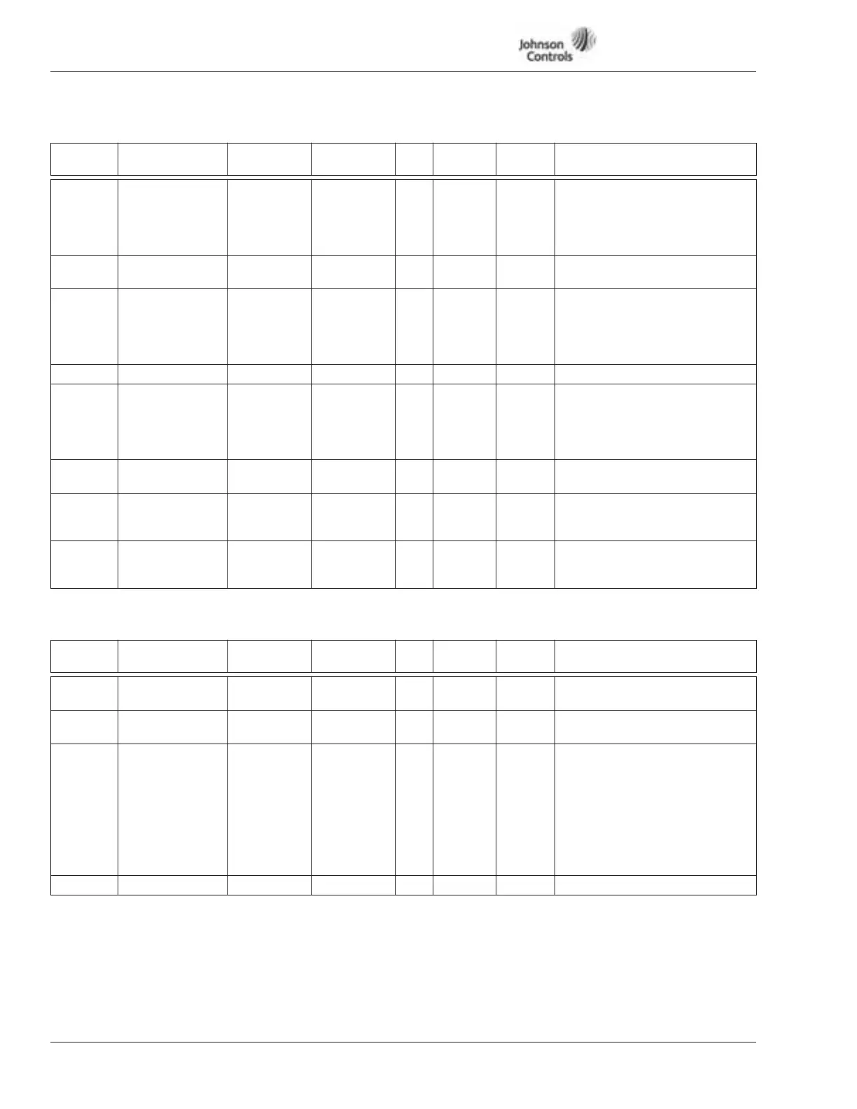
Table 13-4: Output Signals — M1 ➔ G1.3, continued
Drive Control Parameters — M1 ➔ G1.4
Table 13-5: Drive Control Parameters — M1 ➔ G1.4
Code Parameter Min. Max. Unit Default
ID
Number Description
P1.3.14 Act.Sp. Supv Fct 0 2 0 314 Actual Speed Supervision
Function:
0 = Not used
1 = Low limit
2 = High limit
P1.3.15 Act.Sp. Supv Lim 0.0 100.0 % 0.0 315 Actual Speed Supervision Value.
(±1.0% hysteresis)
P1.3.16 Torque Supv Fct 0 2 0 316 Torque Limit Supervision
Function:
0 = Not used
1 = Low limit
2 = High limit
P1.3.17 Torque Supv Lim 0.0 300.0 % 0.0 317 Torque Limit Supervision Value
P1.3.18 TempLim Supv
Fct
0 2 0 318 Temperature Limit Supervision
Function:
0 = Not used
1 = Low limit
2 = High limit
P1.3.19 TempLim Supv
Lim
-50 170 °F 104 319 Temperature Limit Supervision
value
P1.3.20 StartRlyON-Del. 0.0 100.0 s 0.0 320 Relay/Digital output ON-delay
time after start-command is
given.
P1.3.21 StartRlyOFF-Del. 0.0 100.0 s 0.0 321 Relay/Digital output OFF-delay
time after stop-command is
given.
Code Parameter Min. Max. Unit Default
ID
Number Description
P1.4.1 Start Mode 0 1 0 401 0 = Ramp
1 = Flying start
P1.4.2 Stop Mode 0 1 1 402 0 = Coasting
1 = Ramp
P1.4.3 Brake Chopper 0 4 0 403 Brake Chopper Mode Selection.
0 = Brake NO, Test NO
1 = Brake YES(Run), Test YES
(Ready+run)
2 = Brake chopper EXTERNAL,
Test NO
3 = Brake YES(Ready+run), Test
YES (Ready+run)
4 = Brake YES(Run), Test NO
P1.4.4 S-curve Time 0.0 10.0 s 0.0 404 Smooth ratio for S-curve