VSD Series Drives User Manual Powered by Eaton Technology
12-14 For more information visit: www.johnsoncontrols.com LIT-1201828
November 2009
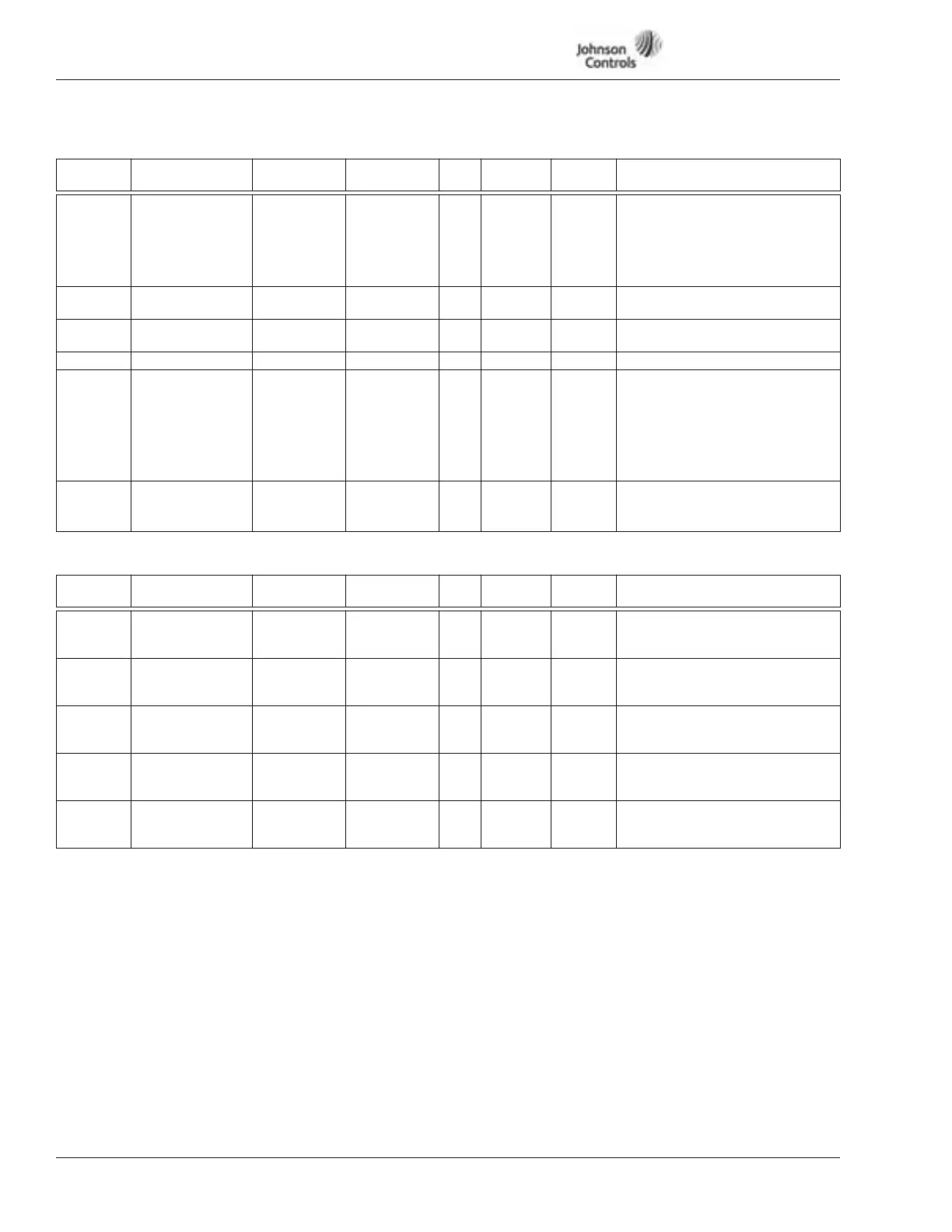
Tables 12-8: Protections — M1 ➔ G1.7, continued
Fieldbus Parameters — M1
➔
G1.8
Table 12-9: Fieldbus Parameters — M1 ➔ G1.8
ID number of parameter or variable to be sent over fieldbus. ID 1 – 20 are Monitoring values, Menu 7 (M7). See Table 12-13.
Code Parameter Min. Max. Unit Default
ID
Number Description
P1.7.15 Underload
Protection
0 3 0 716 0 = No response
1 = Warning
2 = Fault, stop mode after fault
according to ID402
3 = Fault, stop mode after fault
always by coasting
P1.7.16 UP fnom Torque 10.0 150.00 % 50.0 717 Minimum torque allowed when
above FWP.
P1.7.17 UP f0 Torque 5.0 150.00 % 10.0 718 Minimum torque allowed with
zero frequency.
P1.7.18 UP Time Limit 2.00 600.00 s 20.00 719
P1.7.19 Autom. Restart 0 3 0 706 Resets faults. See Page 15-20.
0 = Disabled
1 = Automatically transferred to
Bypass
2 = Reset drive only
3 = Reset drive, if fails,
transferred to Bypass
P1.7.20 Fire Mode Speed 0 100.0 % 100 804 When fire mode input is
triggered, drive will run at fire
mode speed.
Code Parameter Min. Max. Unit Default
ID
Number Description
P1.8.1 FB Data Out1 Sel 0 10000 1
1001 Fieldbus process data output 1
selection.
Default = Actual Speed
P1.8.2 FB Data Out2 Sel 0 10000 5
1002 Fieldbus process data output 2
selection.
Default = Motor Current
P1.8.3 FB Data Out3 Sel 0 10000 8
1003 Fieldbus process data output 3
selection.
Default = Motor Voltage
P1.8.4 FB Data Out4 Sel 0 10000 7
1004 Fieldbus process data output 4
selection.
Default = Motor Power
P1.8.5 FB Data Out5 Sel 0 10000 9
1005 Fieldbus process data output 5
selection.
Default = DC-Link Voltage