VSD Series Drives User Manual Powered by Eaton Technology
15-8 For more information visit: www.johnsoncontrols.com LIT-1201828
November 2009
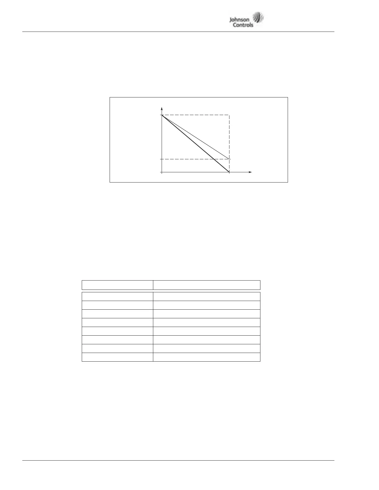
Figure 15-8: Analog Output Invert
Table 15-2: Analog Output Scaling
303 Analog output inversion
Inverts the analog output signal:
Maximum output
signal = Minimum set value
Minimum output signal = maximum set value
304 Analog output minimum
Defines the signal minimum to be either 0 mA or 4 mA (“living zero”). Note the
difference in analog output scaling in parameter ID305 (Figure 15-9).
0 Set minimum value to 0 mA
1 Set minimum value to 4 mA
305 Analog output scale
Scaling factor for analog output.
Signal Max. value of the signal
Output frequency Max frequency (ID102)
Freq. Reference Max frequency (ID102)
Motor speed Motor nom. speed 1xn
mMotor
Output current Motor nom. current 1xI
nMotor
Motor torque Motor nom. torque 1xT
nMotor
Motor power Motor nom. power 1xP
nMotor
Motor voltage 100% x V
nMotor
DC-link voltage 1000 V
Analog Output
Current
20 mA
4 mA
0 mA
0
1.0