Powered by Eaton Technology VSD Series Drives User Manual
LIT-1201828
For more information visit: www.johnsoncontrols.com 15-5
November 2009
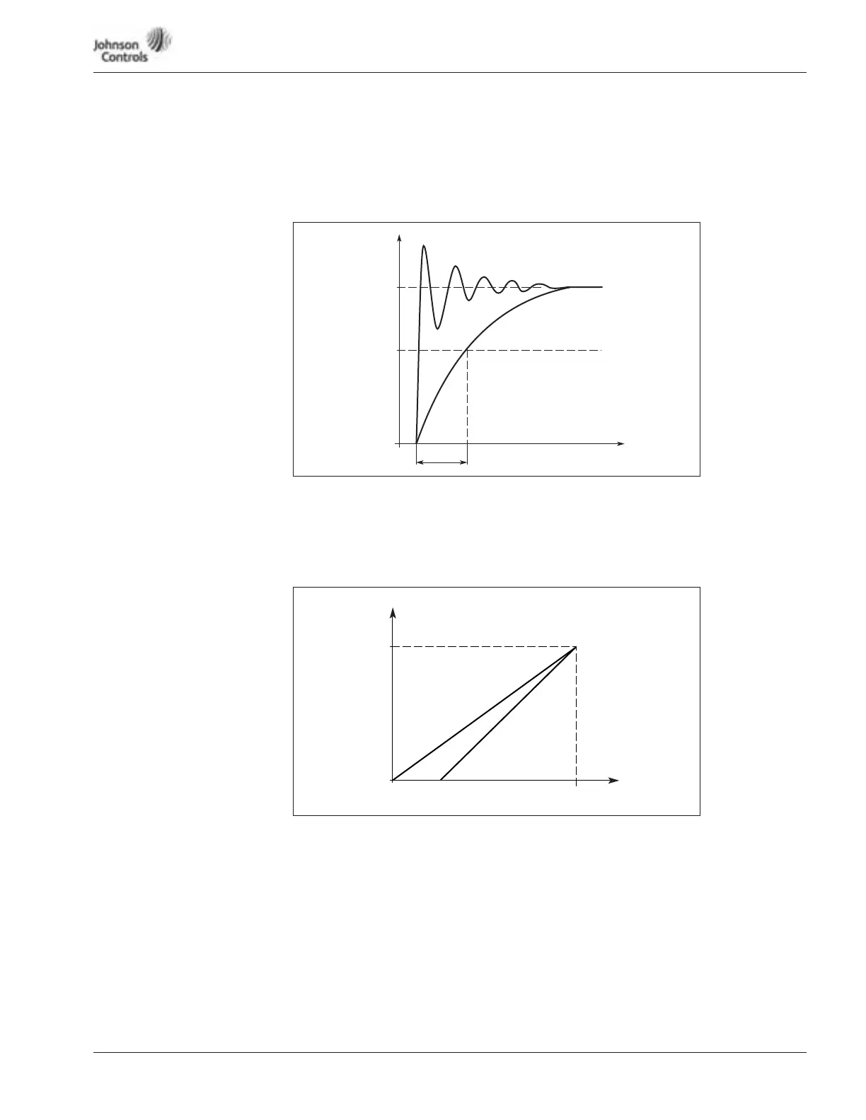
Figure 15-3: AI-1 No Signal Filtering
Figure 15-4: Analog Input AI-2 Scaling
210 AI-1 signal filter time
When this parameter is given a value greater than 0 the function that filters out
disturbances from the incoming analog signal is activated.
A long filtering time makes the regulation response slower. See Figure 15-3.
211 Analog input AI-2 signal range
0 0 – 20 mA
1 4 – 20 mA
212 Analog input AI-2 inversion
See ID209.
213 Analog input AI-2 (I
in
) filter time
See ID210.
Unfiltered Signal
Filtered Signal
%
100%
63%
t [s]
Time
Output
Frequency
Max. Frequency
ID102
ID303
0 4 mA
20 mA
AI-2
(Term. 3.4)