VSD Series Drives User Manual Powered by Eaton Technology
15-6 For more information visit: www.johnsoncontrols.com LIT-1201828
November 2009
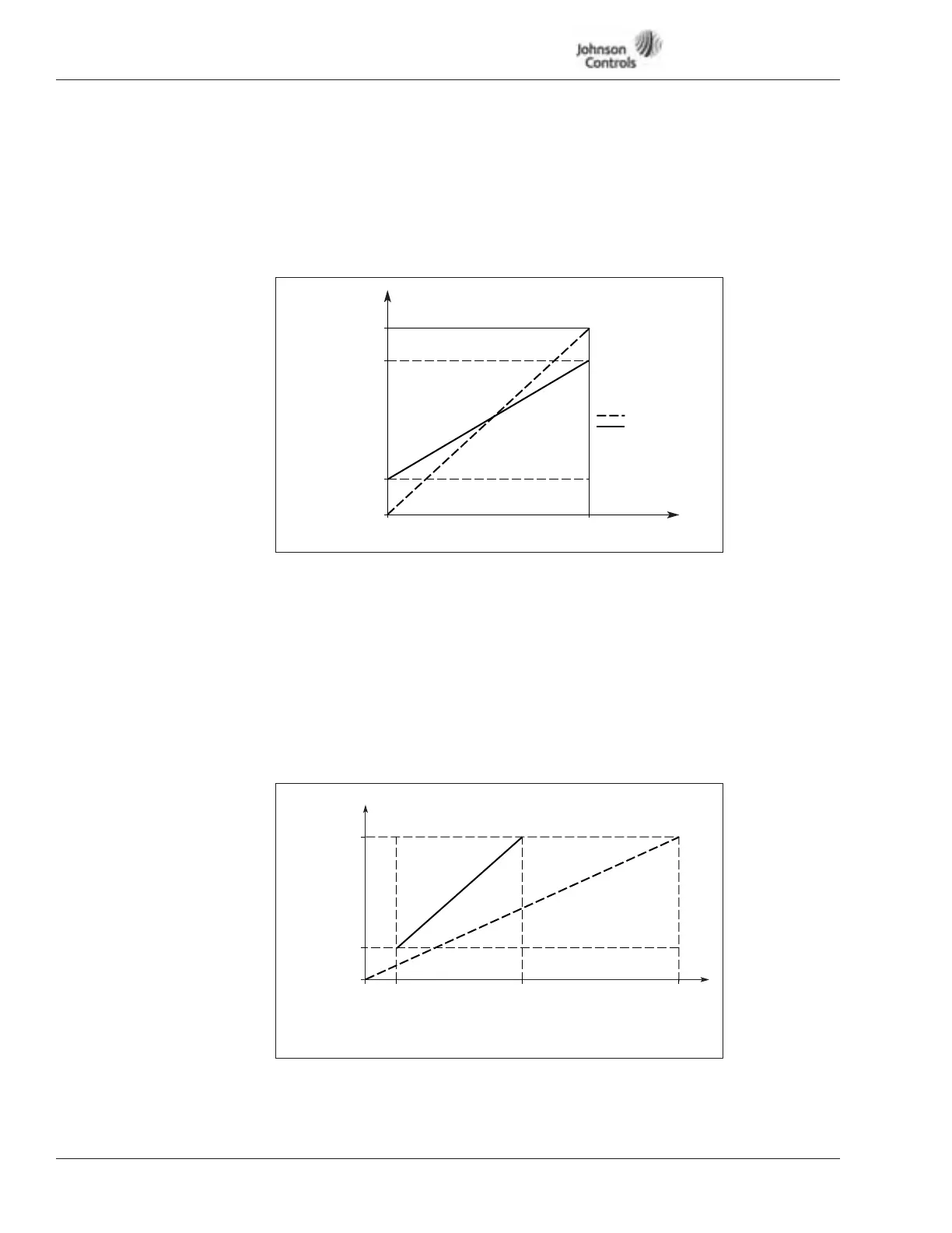
Figure 15-5: Setpoint Scaling
Figure 15-6: Sensor Scaling
214 Setpoint Scale Minimum
Setpoint scaling minimum
215 Setpoint Scale Maximum
Setpoint scaling maximum
Setting value limits 0 ≤ ID214 ≤ ID215 ≤ ID102. If ID215 = 0, scaling is set OFF.
216 Intlk Stop Mode
Coasting:
0 The motor coasts to a halt without any control from the drive, after the
Stop command.
Ramp:
1 After the Stop command, the speed of the motor is decelerated
according to the set deceleration parameters. If the regenerated energy is
high it may be necessary to use an external braking resistor for faster
deceleration.
Output
Frequency
Max. Freq = 100%
ID102
ID215
ID214
0V
0 (4) mA
10V
20 mA
No Scaling
Scaled
Analog Input*
* Selected with
ID113 (AI only)
Sensor Min.
ID1107
0
Sensor Max.
ID1108
Scaled No Scaling
Sensor
Range
50% (5V)
Max.
100%
ID218
(10V or 20 mA)
AI-1 Max.
10% (1V)0%
ID217
(0V or 0 mA)
AI-1 Min.