Powered by Eaton Technology VSD Series Drives User Manual
LIT-1201828
For more information visit: www.johnsoncontrols.com 15-23
November 2009
Figure 15-18: Stall Characteristics Settings
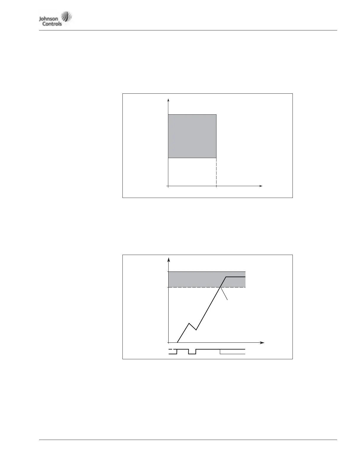
Figure 15-19: Stall Time Count
713 Stall Current Limit
The current can be set to 0.0 – 2*I
H
. For a stall stage to occur, the current must have
exceeded this limit. See Figure 15-18. The software does not allow entering a greater
value than 2*I
H
. If ID107 (nominal current limit of motor) is changed, this parameter is
automatically calculated to 90% of the current limit.
714 Stall Time
This time can be set between 1.0 and 120.
This is the maximum time allowed for a stall stage. The stall time is counted by an
internal up/down counter. If the stall time counter value goes above this limit, the
protection will cause a trip (see ID712).
715 Stall Frequency Limit
The frequency can be set between 1 – f
max
(ID102). For a stall state to occur, the output
frequency must remain below this limit.
Stall Area
ID713
ID715
f
I
Stall
Time Counter
ID714
Stall
Time
No Stall
Trip/Warning
ID712
Trip Area