Powered by Eaton Technology VSD Series Drives User Manual
LIT-1201828
For more information visit: www.johnsoncontrols.com 5-15
November 2009
Note: Set the multimeter to the ohm function, and check the power gµround terminal and
DC bus terminals as indicated in Table 5-12.
Note: Frame 6 and larger use a “Hybrid” rectifier section. “Shown in Service Manual.”
Readings will be different when taking measurements from (B+) DC.
Table 5-12: Static Checks of DC Bus
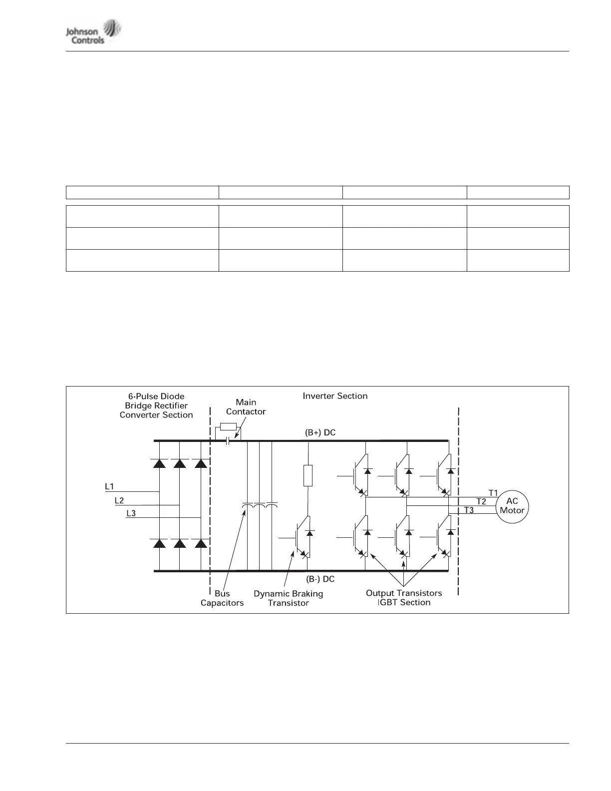
Figure 5-7 is a detailed schematic to aid in performing the static checks.
Continuity Test to Ground
Test L1, L2, L3 to ground.
T1, T2, T3 to ground.
This should read .OL ohms.
Figure 5-7: Schematic for Static Checks (Sample for Frames 4 and 5)
DC Bus Terminal DC Bus Terminal (B-) Ground Terminal (Power) Multimeter Reading
B+ (Overload Check)
Insert red (+) multimeter lead.
Insert black (-) multimeter lead. Not used. .OL
B+ (1st Ohm Check)
Insert black (-) multimeter lead.
Not used. Insert red (+) multimeter lead. O.L
B- (2nd Ohm Check)
Insert black (-) multimeter lead.
Not used. Insert red (+) multimeter lead. O.L