Powered by Eaton Technology VSD Series Drives User Manual
LIT-1201828
For more information visit: www.johnsoncontrols.com 15-27
November 2009
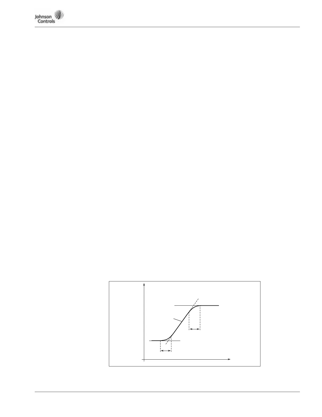
Figure 15-22: Auto Acceleration/Deceleration (S-shaped)
1109 PI controller gain
This parameter defines the gain of the PI controller. If the value of the parameter is set to
1.00 a change of 0.01 in the error value causes the controller output to change by 10%.
1110 PI controller I-time
This parameter defines the integration time of the PI controller. If this parameter is set
to 1.00 second, a change of 10% in the error value causes the controller output to
change by 10.00%/s. If the parameter value is set to 0.00 s the PI controller will operate
as PD controller.
1111 Deadband
Parameter will set ± deadband area for PI controllers error value (Setpoint –
Feedback). When inside the deadband area the PI regulation is stopped and the output
is frozen to current value.
1112 PI controller acting mode
This parameter allows you to invert the error value of the PI controller (and thus the
operation of the PI controller).
0 Forward Acting
1 Reverse Acting
1113 Acceleration time auto mode
Output frequency acceleration time in auto mode.
1114 Deceleration time auto mode
Output frequency deceleration time in auto mode.
1115 Auto Acceleration/Deceleration
ramp shape
Used in Auto Mode and PI control is NOT
active
The start and end of the acceleration and deceleration ramps can be smoothed with these
parameters. Setting a value of 0.0 gives a linear ramp shape which causes acceleration and
deceleration to react immediately to the changes in the reference signal.
Setting a value from 0.1 – 10 seconds for this parameter produces S-shaped acceleration/
deceleration. The acceleration time is determined with ID1113 and ID1114.
ID1115
ID1115
ID1113, ID1114
t
Hz