Powered by Eaton Technology VSD Series Drives User Manual
LIT-1201828
For more information visit: www.johnsoncontrols.com 4-1
November 2009
Chapter 4 — Control Wiring
General Information
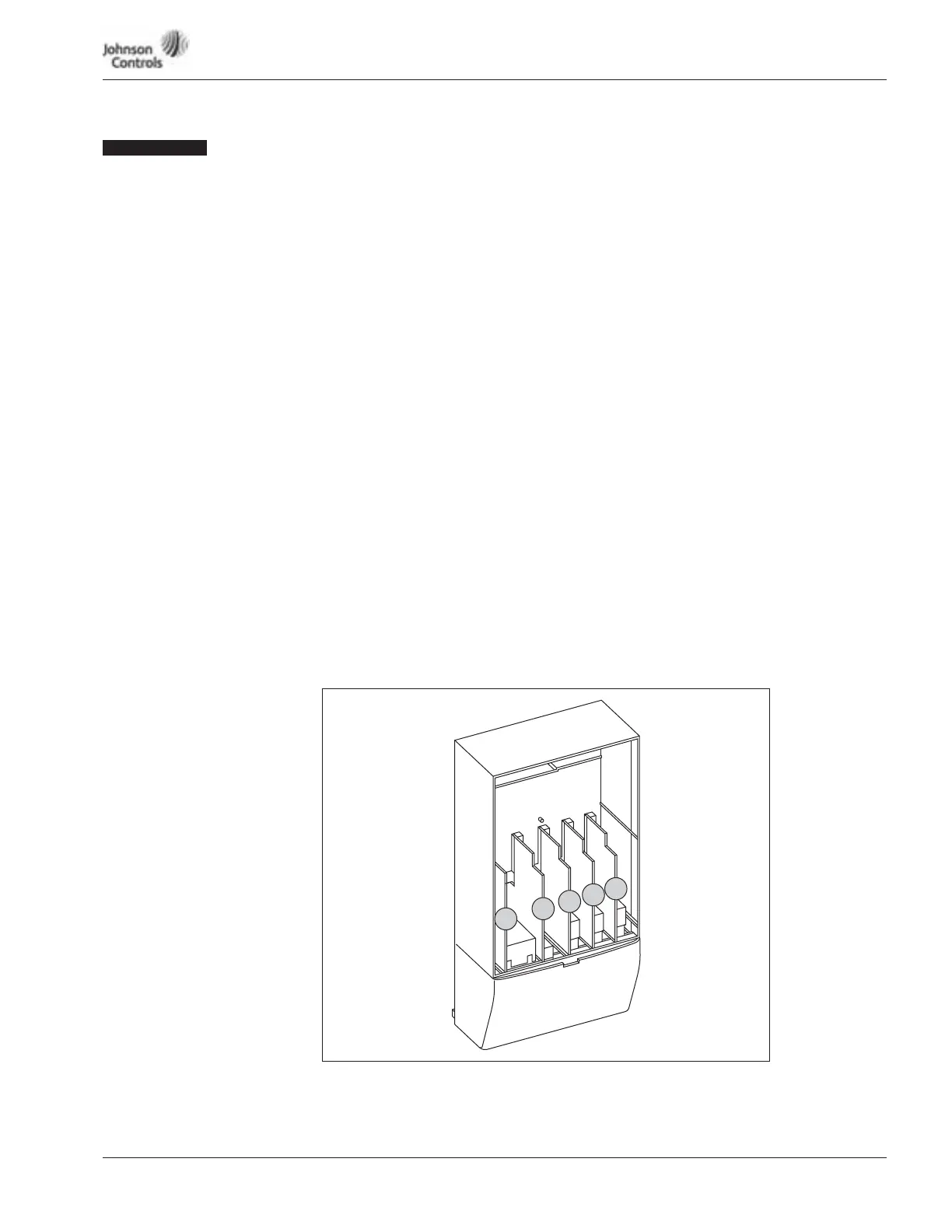
The control unit of the VSD Series drive consists of the control board and various option
boards that plug into the five slot connectors (A to E) of the control board.
Galvanic isolation of the control terminals is provided as follows:
● Control connections are isolated from power, and the GND terminals are permanently
connected to ground.
● Digital inputs are galvanically isolated from the I/O ground.
● Relay outputs are double-isolated from each other at 300V AC.
Option Board General Information
The VSD Series drives can accommodate a wide selection of expander and adapter boards to
customize the drive for your application needs.
The drive’s control unit is designed to accept a total of five option boards. Option boards are
available for normal analog and digital inputs and outputs, for communication and for
additional application-specific hardware.
The VSD Series factory installed standard option board configuration includes an A9 I/O
board and an A2 relay output board, which are installed in slots A and B. For information on
additional option boards, see the VSD Series drives option board manuals.
Note: If your VSD Series drive has been shipped with a factory installed IntelliPass bypass,
the B5 option board is installed in slot C.
Figure 4-1: Option Board Slots
D
C
B
A
E