Powered by Eaton Technology VSD Series Drives User Manual
LIT-1201828
For more information visit: www.johnsoncontrols.com 5-7
November 2009
Table 5-6: Bypass Power Wiring Instructions — NEMA Type 1 IntelliPass/IntelliDisconnect Drive (Continued)
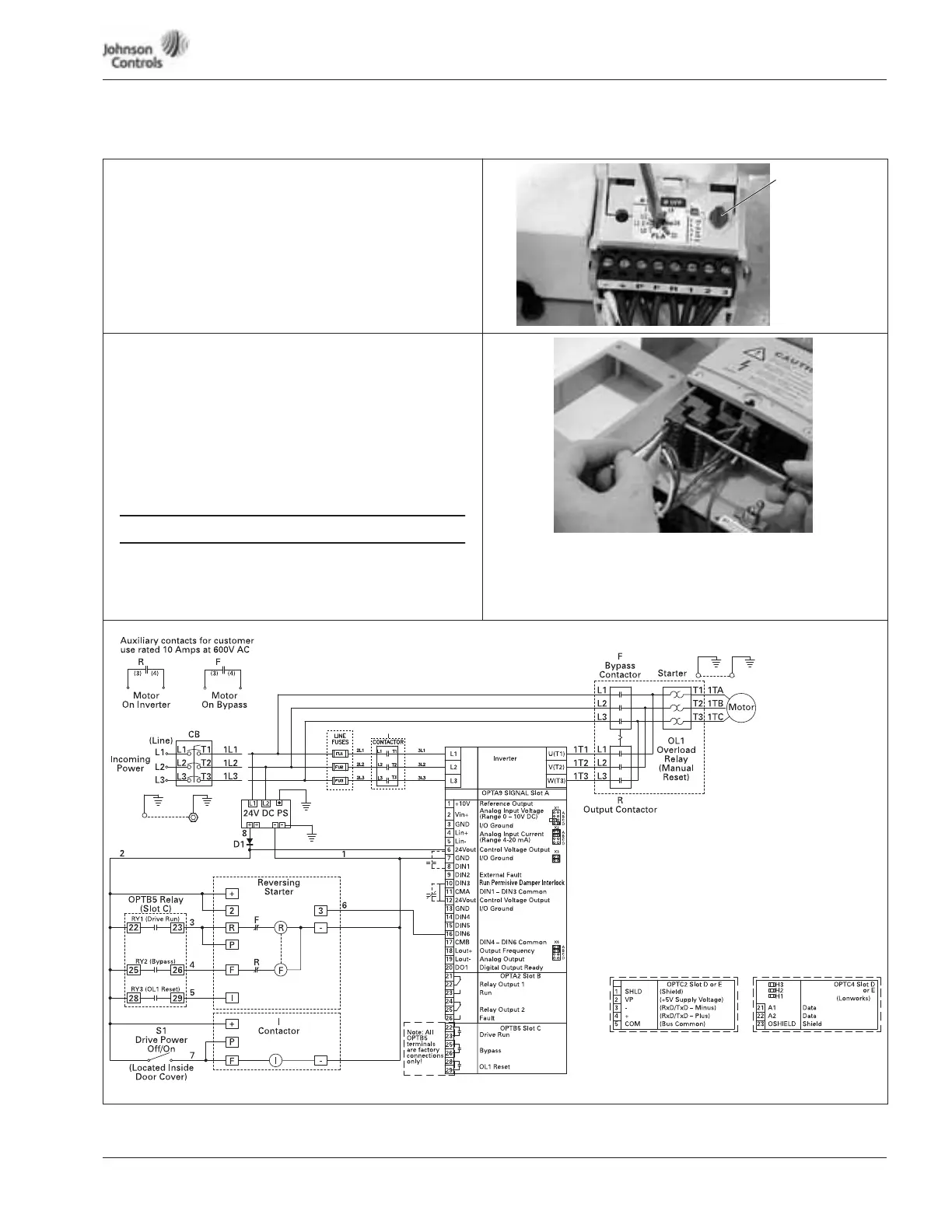
Setting Overload
20. Lift to open the cover on the motor overload, and use a
1/8" flat-blade screwdriver to set the overload amperage to
match the value on the motor nameplate.
21. Turn the auto/manual reset (factory default is manual) on
the motor overload 90° to the auto position.
Control Wiring
22. Use a flat-blade screwdriver to carefully remove the low-
voltage I/O terminal block.
23. Insert the incoming control leads into the terminal block.
Refer to the electrical schematic supplied with the drive.
24. Reinsert the I/O terminal block into the control board.
25. Verify that all other wires to the terminal block are
connected.
26. Terminate control wiring to the OPTA9 and OPTA2 board
(Terminals 1 – 26).
● Run 110 Vac and 24 Vdc control wiring in separate
conduit.
● Communication wire must be shielded.
● RS-232 keypad cable must be less then 25 feet.
Figure 5-3: VSD Series IntelliPass with Three Contactors
Auto/Manual
Reset
CONTROL WIRING
Drive
Ground
Motor
Ground
Note: Optional COMM cards can be supplied
Note: with the drive or as a field option.
Customer
Ground
Drive
Ground
Speed Select 1
Fire Mode
Bypass Overload Fault
Start/Stop
Note: See Figure 3
for Dip X1, X2,
X3, X6 Switch
settings.
OptionalOptional