VSD Series Drives User Manual Powered by Eaton Technology
15-26 For more information visit: www.johnsoncontrols.com LIT-1201828
November 2009
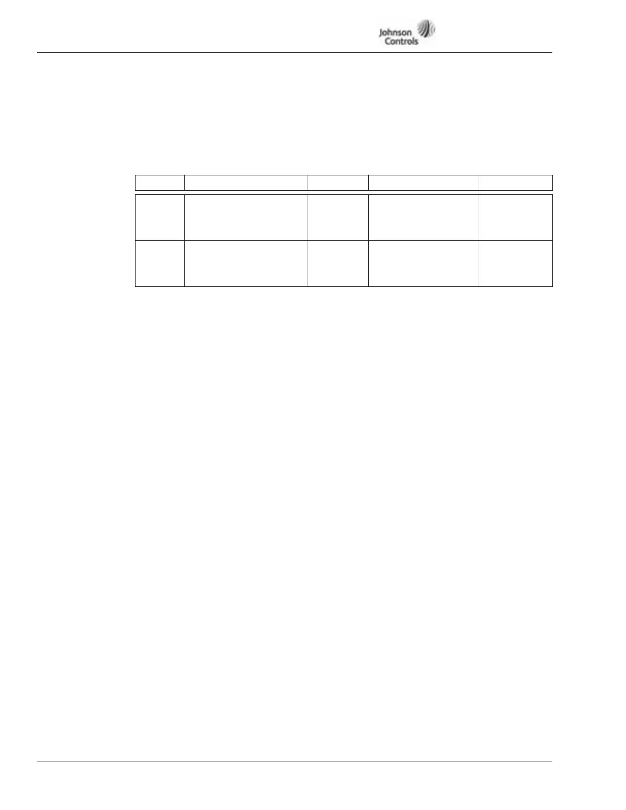
Table 15-5: Fieldbus Parameters
1001
to
1008
Fieldbus Data Out
These parameters can be used to send parameter or monitoring values to fieldbus.
The values can be selected by using ID numbers.
ID Data Default Description Unit
1001
1002
1003
1004
FB Data Out 1 Select
FB Data Out 2 Select
FB Data Out 3 Select
FB Data Out 4 Select
1
5
8
7
Actual Speed
Motor Current
Motor Voltage
Motor Power
rpm
A
V
%
1005
1006
1007
1008
FB Data Out 5 Select
FB Data Out 6 Select
FB Data Out 7 Select
FB Data Out 8 Select
9
20
18
19
DC Bus Voltage
Status Word
Active Fault Code
Active Warning Code
V
—
—
—
1011 PI Setpoint Default
PI-regulators default setpoint. This parameter is set with Start-Up Wizard. Parameter
not available in Remote Input application.
1101 US/Metric Units
(Duct, building, pressure and temperature applications only.)
0 US units
1 Metric units
1102 PI Setpoint Min. Limit Default: Same value as ID1107.
PI Setpoint limitation minimum value.
1103 PI Setpoint Max. Limit Default: Same value as ID1108.
PI Setpoint limitation maximum value.
1104 PI Setpoint Ramp Time
Defines the time during which the PI controller reference rises from 0% to 100% or
falls from 100% to 0%.
1106 PI-Controller Input Source
0 AI-1 (control board)
1 AI-2 (control board)
2 Fieldbus (Actual value 1: FBProcessDataIN1)
3 Min. Both
4 Max. Both
5 Ave. Both
1107 Sensor Minimum Scale
Feedback sensor minimum output value. See Figure 15-6.
1108 Sensor Maximum Scale
Feedback sensor maximum output value. See Figure 15-6.