VSD Series Drives User Manual Powered by Eaton Technology
3-6 For more information visit: www.johnsoncontrols.com LIT-1201828
November 2009
Standard Wiring Diagrams and Terminal Locations
Power and Motor Wiring Terminal Schematics for VSD Series Drives
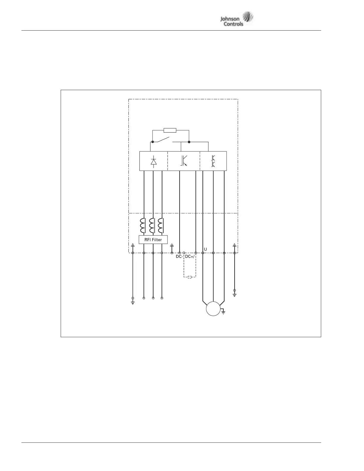
The following wiring diagrams show the line and motor connections of the drive.
Figure 3-3: Principle Wiring Diagram of VSD Series Power Unit,
FR4, FR5 and FR6
Note: When using a 1-phase supply, for units rated for such, connect the input power to
terminals L1 and L2. Refer to Tables A-2 and A-3 in Appendix A.
N
L
L
Br
k
O
tio
M
~
Load
Se
arate Condui
Line
Se
arate Condui
Power
Board
n
r
B
r
230V 1 - 20 h
480V 1-1/2 - 40 h
575V 3 - 30 h
Note:
Integrated Brake
Chopper Circuit Not
Included on 575V units.
VT