Powered by Eaton Technology VSD Series Drives User Manual
LIT-1201828
For more information visit: www.johnsoncontrols.com 3-7
November 2009
Table 3-8: Control Wiring Instructions — NEMA Type 1/12 Open Drives (Continued)
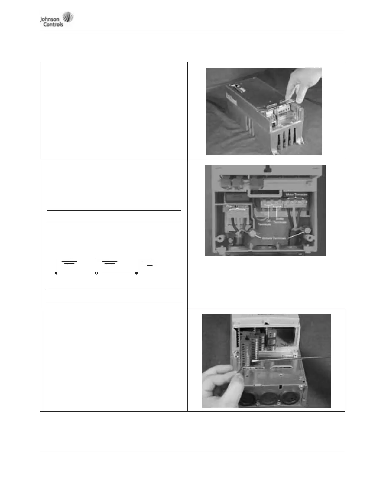
Power Wiring
4. If conduit is being used, attach the wiring plate to it.
5. Pass the motor and input power wires/cables through the
holes of the wiring plate.
6. If shielded cable is used, connect the shields of the input
line power cable and the motor cable to the motor and
power ground terminals of the VSD Series drive.
Power Wiring/Grounding
7. Wire power terminals, motor terminals, and grounding
terminals per diagram. Power and Motor leads must be in
separate conduit.
Note: Do not wire motor loads to B- B+ R-. This will cause
damage.
● Run motor cables in separate conduit.
● DO NOT RUN CONTROL WIRES in same conduit
● Cables sized per NEC.
● Provide low impedance ground between drive and
motor.
Control Wiring
8. Wire the control terminals following the details for the
specific option boards shown on the following pages.
Note: For ease of access, the option board terminal blocks can
be unplugged for wiring.
Note: If using conduit or Seal Tite for control wiring for Frame
4, you must order NEMA Type 12 kit.
GROUND WIRING
Utility Drive Motor Ground
(Inside Motor Conduit Box)
IMPORTANT: Improper grounding could result in damage to the
motor and/or drive and could void warranty