VSD Series Drives User Manual Powered by Eaton Technology
15-2 For more information visit: www.johnsoncontrols.com LIT-1201828
November 2009
Table 15-1: Selections for IDs 112, 113, 114 and 115
112 Start Source Hand
Start/Stop/Reverse control location in Hand mode:
1 Keypad
2 DI-1
3 I/O Three-Wire start
Note: When Three-Wire mode selected, DI-2 is automatically selected as stop
command.
113 Setpoint Source Hand
Speed setpoint source selection in Hand Mode.
0 analog input AI-1
1 analog input AI-2
2 Keypad
3 Motor potentiometer
114 Start Source Auto (PI-Control)
Start/Stop/Reverse control location in Auto mode:
1 Keypad
2 DI-1
3 I/O Three-Wire
4 Fieldbus
Note: When Three-Wire mode selected, DI-2 is automatically selected as stop
command.
115 Setpoint Source Auto (PI-Control)
PI Setpoint Source selection:
0 Analog input AI-1
1 Analog input AI-2
2 Keypad
3 Motor potentiometer
4 Fieldbus
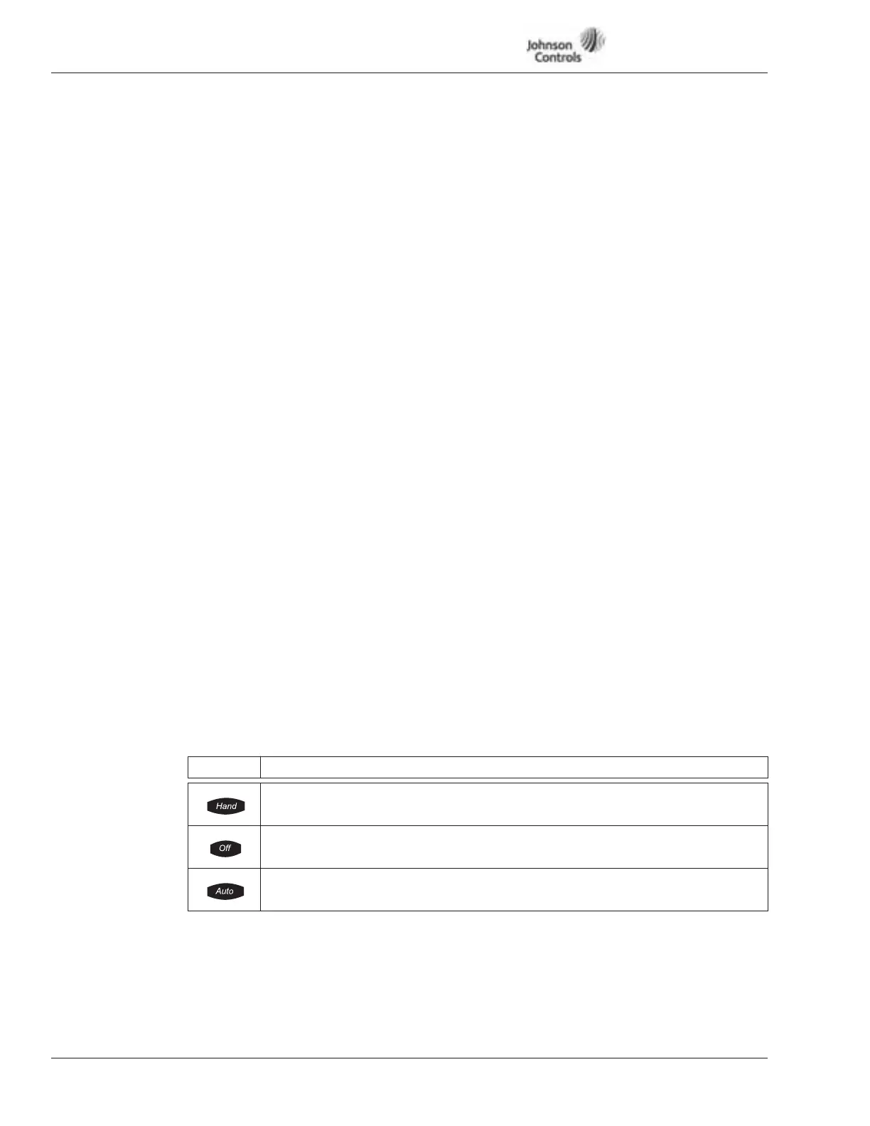
Indicator Description
Hand
Indicates that HAND has been chosen in the HOA control mode.
Off
Indicates that the VSD Series drive is not ready to operate. (Ready-indicator is OFF).
Auto
Indicates that AUTO has been chosen in the HOA control mode.
116 Preset Speed
This parameter determines the frequency reference for Preset Speed 1 operation
when either DI-2, DI-4, DI-5 or DI-6 are set to control Speed Select 1 and closed.
100% = Max. Frequency (ID102)