VSD Series Drives User Manual Powered by Eaton Technology
3-4 For more information visit: www.johnsoncontrols.com LIT-1201828
November 2009
Installation Instructions
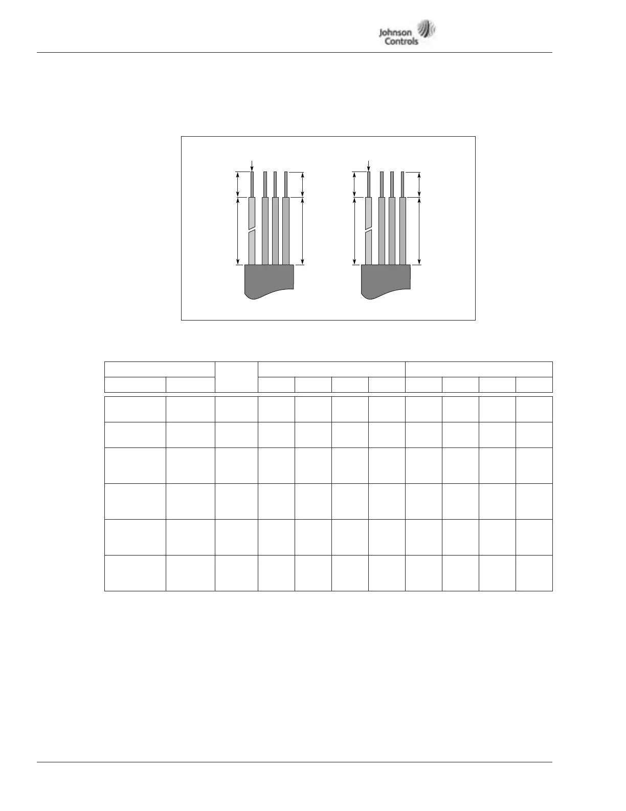
Strip the motor and power cables as shown in Figure 3-1 and Table 3-7.
Figure 3-1: Input Power and Motor Cable Stripping and Wire Lengths
Table 3-7: Power and Motor Cable Stripping Lengths
Product
Frame
Size
Power Wiring in Inches (mm) Motor Wiring in Inches (mm)
Horsepower Voltage A1 B1 C1 D1 A2 B2 C2 D2
1 – 3
1-1/2 – 7-1/2
230
480
FR4 0.59
(15)
1.38
(35)
0.39
(10)
0.79
(20)
0.28
(7)
1.97
(50)
0.28
(7)
1.38
(35)
5 – 10
10 – 20
230
480
FR5 0.79
(20)
1.57
(40)
0.39
(10)
1.18
(30)
0.79
(20)
2.36
(60)
0.39
(10)
1.57
(40)
15 and 20
25 – 40
3 – 30
230
480
575
FR6 0.79
(20)
3.54
(90)
0.59
(15)
2.36
(60)
0.79
(20)
3.54
(90)
0.59
(15)
2.36
(60)
25 – 40
50 – 75
40 – 50
230
480
575
FR7 0.98
(25)
4.72
(120)
0.98
(25)
4.72
(120)
0.98
(25)
4.72
(120)
0.98
(25)
4.72
(120)
50 – 75
100 – 150
60 – 100
230
480
575
FR8 1.1
(28)
9.45
(240)
1.1
(28)
9.45
(240)
1.1
(28)
9.45
(240)
1.1
(28)
9.45
(240)
100
200 – 250
125 – 200
230
480
575
FR9 1.1
(28)
11.61
(295)
1.1
(28)
11.61
(295)
1.1
(28)
11.61
(295)
1.1
(28)
11.61
(295)
A1
B1
C1
D1
A2
B2
C2
D2
Power Motor
Ground Ground