VSD Series Drives User Manual Powered by Eaton Technology
13-2 For more information visit: www.johnsoncontrols.com LIT-1201828
November 2009
Control Input/Output
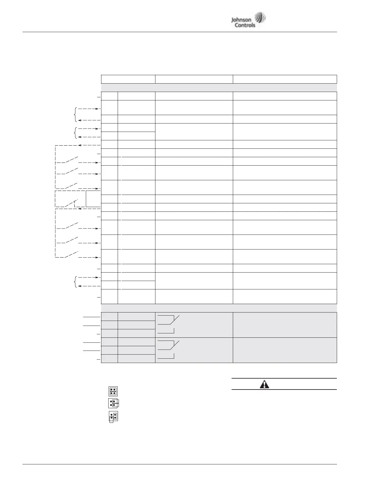
Table 13-1: Pressure Control Application Default I/O Configuration
Note: For more information on jumper selections, see Chapter 4.
Terminal Signal Description
OPTA9
1 +10V DC
ref
Reference output Voltage for potentiometer, etc.
2 AI-1+ Analog input, voltage range
0 – 10V DC
Voltage input for PI setpoint or
feedback (Programmable)
3 AI-1- I/O Ground Ground for reference and controls
4 AI-2+ Analog input, current range
0 – 20 mA
Current input for PI setpoint or
feedback (Programmable)
5 AI-2-
6 24V DC Control voltage output Voltage for switches, etc. max 0.1A
7 GND I/O ground Ground for reference and controls
8 DI-1 Start/Stop Control Contact closed = start
9 DI-2 External fault input
(programmable)
Contact closed = fault
Contact open = no fault
10 DI-3 External Interlock
(programmable)
Contact closed = OK
Open = Interlocked
11 CMA Common for DI-1 – DI-3 Connect to GND or 24V DC
12 24V DC Control voltage output Voltage for switches (see terminal 6)
13 GND I/O ground Ground for reference and controls
14 DI-4 Speed Select 1
(programmable)
Contact closed = Speed Select 1
15 DI-5 Fire Mode
(programmable)
Contact closed = Fire Mode active
16 DI-6 Overload relay (IntelliPass)
(programmable)
Contact open = no fault
Contact closed = fault
17 CMB Common for DI-4 – DI-6 Connect to GND or 24V DC
18 AO-1+ Output frequency
Analog output
Programmable
Range 0 – 20 mA, R
L
max. 500W
19 AO-1
20 DO-1 Digital output
READY
Programmable
Open collector, I ≤ 50 mA, V ≤ 48V DC
OPTA2
21 RO-1 Relay output 1 Programmable
Drive RUN is default.
22 RO-1
23 RO-1
24 RO-2 Relay output 2 Programmable
Drive FAULT is default.
25 RO-2
26 RO-2
0 to 10V DC
(Factory Default)
4 to 20 mA
(Factory Default)
0 to 20 mA
(Factory Default)
External
Interlock
Wiring
External
Interlock
Wiring
21-22 Opens on RUN
22-23 Closes on RUN
Defaults:
24-25 Opens on FAULT
25-26 Closes on FAULT
CMB and CMA Internally Connected
and Isolated from Ground
X3 Jumper Setting — CMA and CMB Grounding
CMB Connected to Ground
CMA Connected to Ground
CMB Isolated from Ground
CMA Isolated from Ground
CAUTION
Unattended start will occur if power
is supplied with Start Command
activated.