VSD Series Drives User Manual Powered by Eaton Technology
D-2 For more information visit: www.johnsoncontrols.com LIT-1201828
November 2009
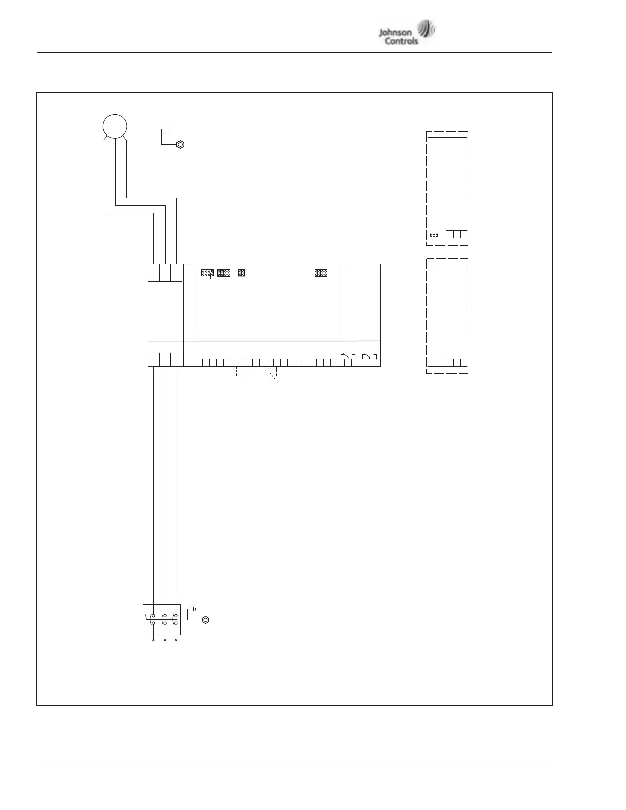
Figure D-2: VSD Series IntelliPass Disconnect
1TA
1TB
1TC
Motor
L1
(Line)
Incoming
Power
L2
L3
CB
T1
T2
T3
L1
L2
L3
1L1
1L2
1L3
(Lonworks)
21
22
23
A1
A2
OShield
Data
Data
Shield
OPTC4 Slot D or E
H3
H2
H1
4
5
1
2
3
(RxD/TxD – Plus)
(Bus Common)
(Shield)
(+5V Supply Voltage)
(RxD/TxD – Minus)
+
COM
Shield
VP
–
OPTC2 Slot D or E
Note: Optional Communication Cards
Can Be Supplied with the Drive
or as a Field Option.
OPTA9 SIGNAL Slot A
L1
Inverter
L2
L3
U(T1)
V(T2)
W(T3)
+10V1
Reference Output
Vin+2
Analog Input Voltage
(Range 0 – 10V DC)
GND3
I/O Ground
Lin+4
Lin-5
Analog Input Current
(Range 4-20 mA)
X3
A
X2
B
C
D
A
X1
B
C
D
24Vout6
GND7
DIN18
Control Voltage Output
I/O Ground
Start/Stop
A
X6
B
C
D
Digital Output Ready
26
21
22
23
24
25
OPTA2 Slot B
Relay Output 1
Run
Relay Output 2
Fault
DIN29
DIN310
CMA11
24Vout12
GND13
DIN414
DIN515
DIN616
CMB17
Lout+18
Lout-19
DO120
External Fault
Run Permisive IP Interlock
DIN1 – DIN3 Common
Control Voltage Output
I/O Ground
Speed Select 1
Fire Mode
Bypass Overload Relay Fault
DIN4 – DIN6 Common
Output Frequency
Analog Output