Powered by Eaton Technology VSD Series Drives User Manual
LIT-1201828
For more information visit: www.johnsoncontrols.com 2-1
November 2009
Chapter 2 — Mounting Open TYPE 1, TYPE 12 Drives
VSD Series open drives may be mounted side-by-side or stacked vertically, as outlined in the
following section.
Note: See Chapter 5 for mounting TYPE 1, TYPE 12 and TYPE 3R IntelliPass drives.
Space Requirements
To ensure proper air circulation and cooling, follow the guidelines below.
Table 2-1: Space Requirements for Mounting a VSD Series Drive
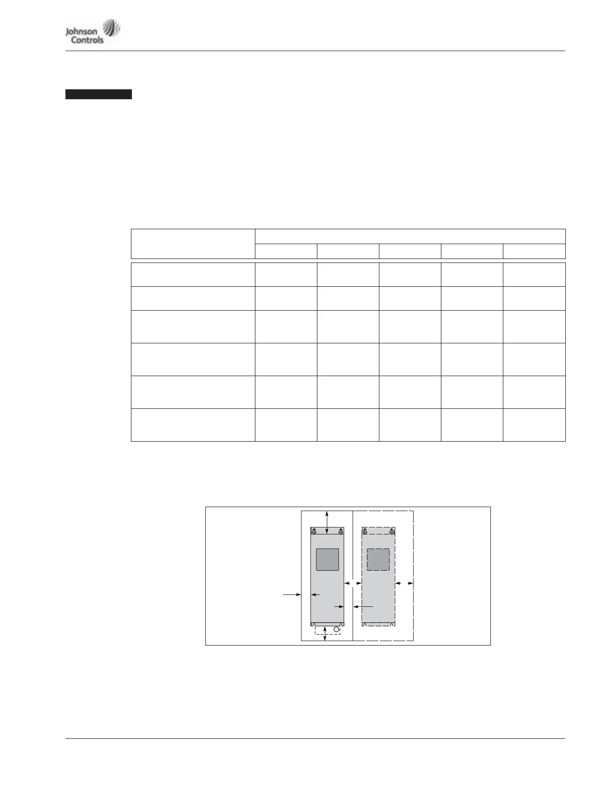
Dimensions represent the minimum clearance needed when mounting a drive. See Figure 2-1 below.
A = clearance around the VSD Series drive.
A
2
= clearance needed to change the fan without disconnecting the motor cables.
B = distance between adjacent VSD Series drives or between the VSD Series drive and an enclosure wall.
C = clearance above the VSD Series drive.
D = clearance below the VSD Series drive.
Minimum clearance below the VSD Series drive needed to change the fan.
Figure 2-1: Mounting Space Requirements
If several units are mounted above each other, the clearance between the drives should equal
C + D (see Table 2-1 and Figure 2-1 above). In addition, the outlet air used for cooling the
lower unit must be directed away from the inlet air used by the upper unit.
Drive Type
Variable Torque Rating
Approximate Dimensions in Inches (mm)
AA
2
BCD
230V, 1 – 3 hp
480V, 1-1/2 – 7-1/2 hp
0.8 (20) 0.8 (20) 3.9 (100) 2.0 (50)
230V, 5 – 10 hp
480V, 10 – 20 hp
0.8 (20) 0.8 (20) 4.7 (120) 2.4 (60)
230V, 15 – 20 hp
480V, 25 – 40 hp
575V, 3 – 30 hp
1.2 (30) 1.2 (30) 6.3 (160) 3.1 (80)
230V, 25 – 40 hp
480V, 50 – 75 hp
575V, 40 – 50 hp
3.1 (80) 3.1 (80) 11.8 (300) 3.9 (100)
230, 50 – 75 hp
480V, 100 – 150 hp
575V, 60 – 100 hp
3.1 (80) 5.9 (150) 3.1 (80) 11.8 (300) 7.9 (200)
230V, 100 hp
480V, 200 – 250 hp
575V, 125 – 200 hp
2.0 (50) 3.1 (80) 15.7 (400) 9.8 (250)
13.8
(350)
D
B
C
B
A
A
2
A
A
2
2