VSD Series Drives User Manual Powered by Eaton Technology
5-16 For more information visit: www.johnsoncontrols.com LIT-1201828
November 2009
IntelliPass Control Wiring Instructions
Use the instructions and diagrams in Chapter 4 “Control Wiring” for wiring standard option
boards A9 and A2.
In addition to these two boards, the IntelliPass Bypass includes option board B5, which is
described in the following section.
Wiring Option Board B5
● This board is to be mounted in slot C.
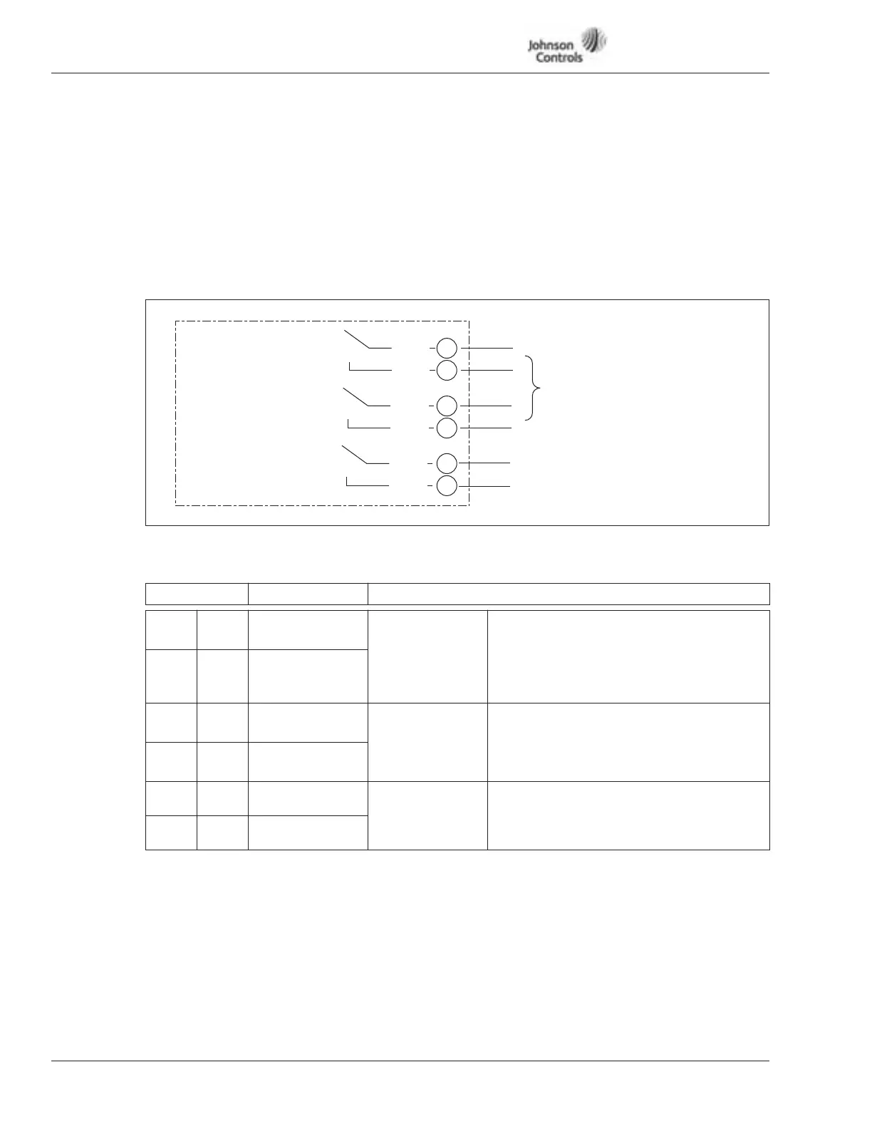
Figure 5-8: Option Board B5 Wiring Diagram
Table 5-13: Option Board B5 Terminal Descriptions
Terminal Signal Description and Parameter Reference
22 RO-1/1 Common Drive Run Switching Capacity:
24V DC / 8A
250V AC / 8A
125V DC / 0.4A
Min Switching Load: 5V/10 mA
Continuously: <2 Arms
23 RO-1/2 Normally Open
25 RO-2/1 Common Bypass Switching Capacity:
24V DC / 8A
250V AC / 8A
125V DC / 0.4A
26 RO-2/2 Normally Open
28 RO-3/1 Common Overload Reset Switching Capacity:
24V DC / 8A
250V AC / 8A
125V DC / 0.4A
29 RO-3/2 Normally Open
Overload
Reset
26
25
29
28
23
22
RO-1/1
RO-1/2
RO-2/1
RO-2/2
RO-3/1
RO-3/2
Max. Current/Voltage Switching:
<8A / 24V DC
<0.4A / 125V DC
<8A / 250V AC
Continuously <2 Arms
Basic Relay Board B5
Drive Run
Bypass
Both Relays Turn On in Bypass Operation
Only RO-1 Turns On for Drive Run