Powered by Eaton Technology VSD Series Drives User Manual
LIT-1201828
For more information visit: www.johnsoncontrols.com 15-21
November 2009
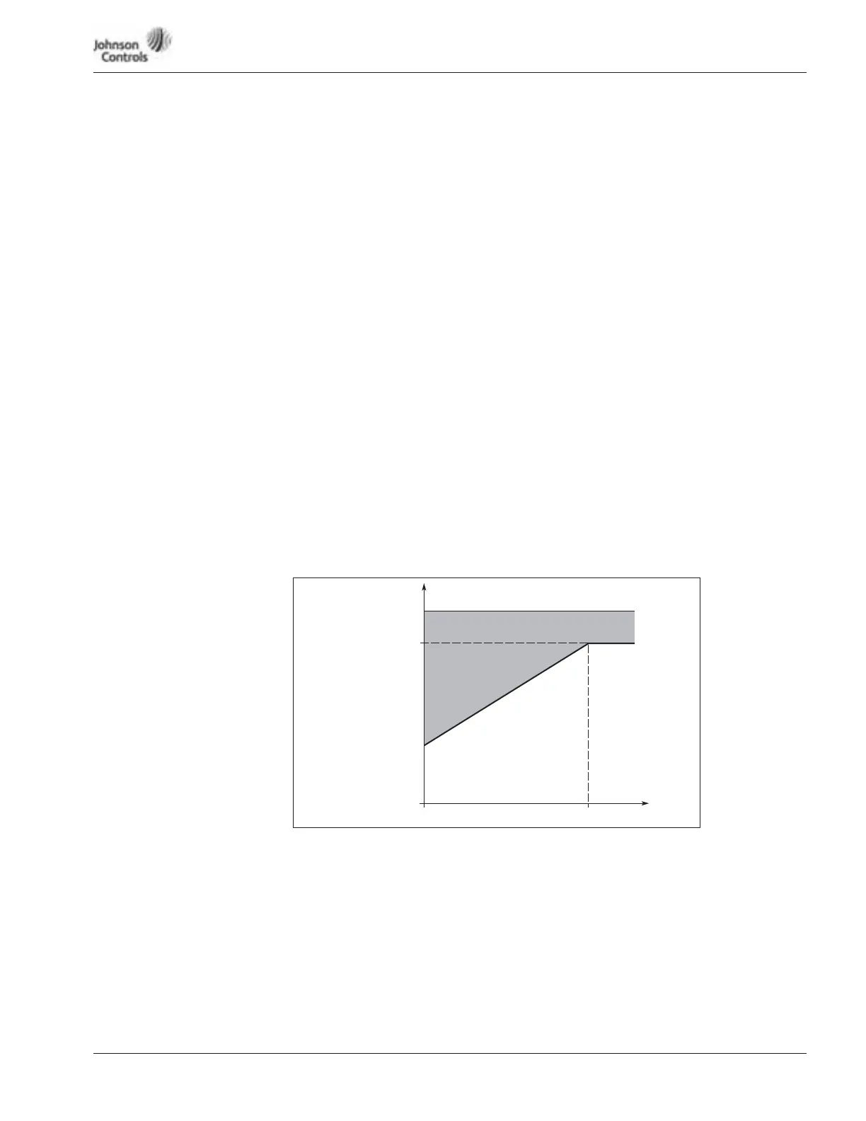
Figure 15-16: Motor Thermal Current I
T
Curve
707 Motor Thermal Protection
0 No response
1 Warning
2 Fault, stop mode after fault according to ID402
3 Fault, stop mode after fault always by coasting
If tripping is selected the drive will stop and activate the fault stage. Deactivating the
protection, ie. setting parameter to 0, will reset the thermal stage of the motor to 0%.
708 Motor Thermal Protection: Motor Ambient Temperature Factor
The factor can be set between -100.0% – 100.0%.
709 Motor Thermal Protection: Motor Cooling Factor at Zero Speed
The current can be set between 0 – 150.0% x I
nmotor
. This parameter sets the value for
thermal current at zero frequency. See Figure 15-16.
The default value is set assuming that there is no external fan cooling the motor. If an
external fan is used, this parameter can be set to 90% (or even higher).
Note: The value is set as a percentage of the motor nameplate data, ID108 (Nominal
current of motor), not the drive’s nominal output current. The motor’s nominal
current is the current that the motor can withstand in direct on-line use without
being overheated.
If nominal current of motor (ID108) is changed, this parameter is automatically
restored to the default value. Setting this parameter does not affect the maximum
output current of the drive, which is determined by ID107 alone.
Par. ID709 = 40%
Overload Area
ff
n
P
cooling
I
T
0
100%