Powered by Eaton Technology VSD Series Drives User Manual
LIT-1201828
For more information visit: www.johnsoncontrols.com 6-19
November 2009
Expander Board Menu (M6)
The Expander Board Menu makes it possible for the user to:
● to see what expander boards are connected to the control board and
● to access and edit the parameters associated with the expander board.
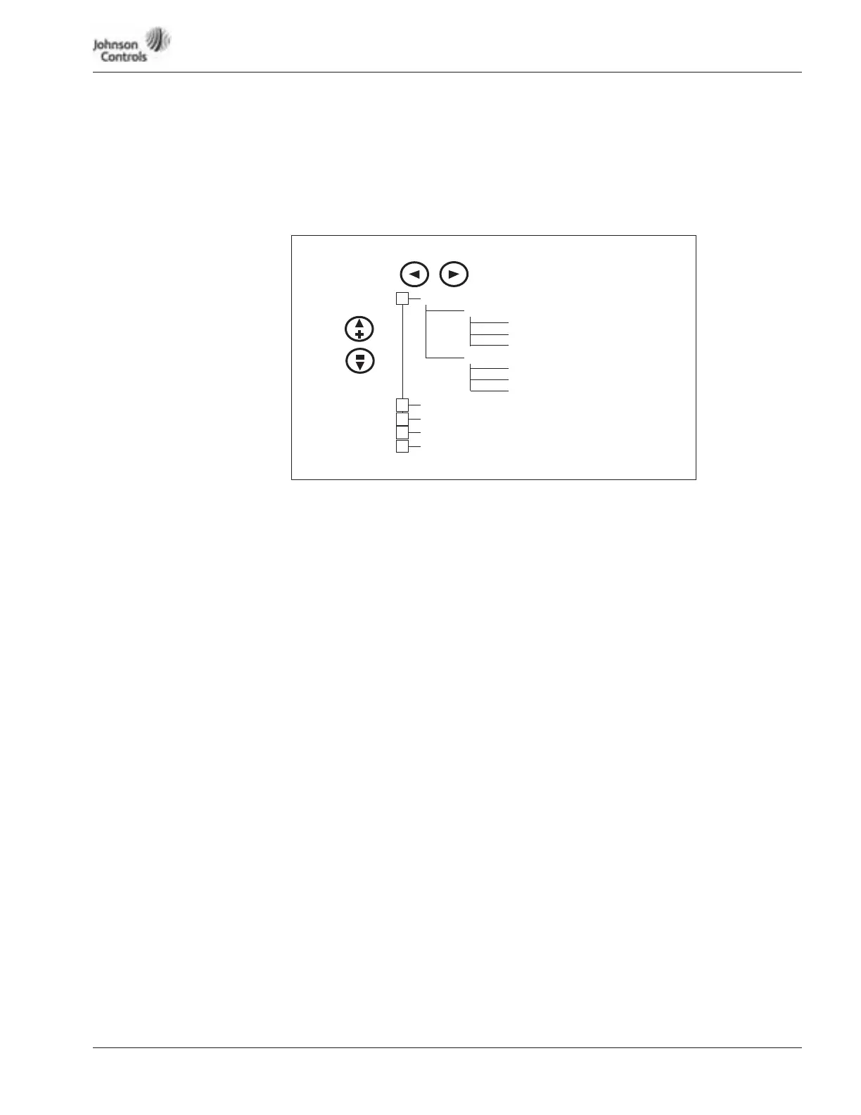
Figure 6-9: Expander Board Menu Structure
Example of Expander Board Parameters for Option Board A9
P6.1.1.1
AI-1 Mode
Range: 1 – 5 Default: 3
AI-1 Mode
Analog Input 1 input options:
1 0 – 20 mA
2 4 – 20 mA
3 0 – 10V DC
4 2 – 10V DC
5 -10 – +10VP
P6.1.1.2
AI-2 Mode
Range: 1 – 5 Default: 1
AI-2 Mode
Analog Input 2 input options:
1 0 – 20 mA
2 4 – 20 mA
3 0 – 10V DC
4 2 – 10V DC
5 -10 – +10VP
Values 2 – 5 require changing pins. See Figure [?] on Page [?]. {THIS WAS DELETED}
P6.1.1.3
AO-1 Mode
Range: 1 – 4 Default: 1
A0-1 Mode
Analog Output 1 output options:
1 0 – 20 mA
2 4 – 20 mA
3 0 – 10V DC
4 2 – 10V DC
G6.1 “A: OPTA9”
G6.2 “B: ”
G6.3 “C: ”
G6.4 “D: ”
G6.5 “E: ”
(Slot A Option Board)
(Slot B Option Board)
(Slot C Option Board)
(Slot D Option Board)
(Slot E Option Board)
G6.1.1 Parameters
P6.1.1.1 AI-1 Mode
P6.1.1.3 AO-1 Mode
G6.1.2 I/O-monitor
P6.1.1.2 AI-2 Mode
+
+
+
+
+
V6.1.2.1
. . .
V6.1.2.10
 Loading...


