Powered by Eaton Technology VSD Series Drives User Manual
LIT-1201828
For more information visit: www.johnsoncontrols.com 5-11
November 2009
Table 5-9: Bypass Power Wiring Instructions — Enclosed NEMA Type 12/3R (Continued)
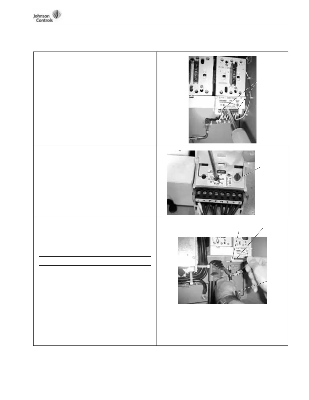
Motor Wiring
11. Use your first and second fingers and simultaneously
push down to release the two orange retaining clips (one
on each side of the 24V DC motor overload terminal
block).
12. If necessary, use a flat-blade screwdriver to carefully
remove the terminal block in a straight plane to avoid
damaging it.
Setting Motor Overload
13. Lift to open the cover on the motor overload, and use a
1/8" flat-blade screwdriver to set the overload amperage
to match the value on the motor nameplate.
14. Turn the auto/manual reset (factory default is manual) on
the motor overload 90° to the auto position.
Motor Wiring
15. Connect the motor leads to the motor overload terminals
labeled 1TA, 1TB and 1TC.
16. Using the appropriate metric Allen wrench (2.5 mm, 3 mm
or 4 mm), tighten each overload terminal per the
specifications in the contactor user’s manual.
An SAE allen wrench will damage the terminals,
and the motor overload will need to be replaced
(not covered by warranty).
17. Using the torque wrench, tighten each terminal to
the torque value found in the appropriate user’s
manual supplied with the drive.
18. Reinsert the motor overload terminal block.
19. Connect the motor ground wire to the ground stud.
Note:
● Run motor cables in separate conduit.
● Do not run control wires in same conduit.
● Size motor leads per NEC.
● Provide low impedance ground.
Orange
Retaining Clips
Bypass
Contactor
Assembly
Auto/Manual
Reset
Bypass
Contactor
Assembly
MOTOR WIRING
Motor Leads
Motor
Overload
Terminals
Motor
Ground
Stud