Powered by Eaton Technology VSD Series Drives User Manual
LIT-1201828
For more information visit: www.johnsoncontrols.com 5-13
November 2009
Table 5-9: Bypass Power Wiring Instructions — Enclosed NEMA Type 12/3R (Continued)
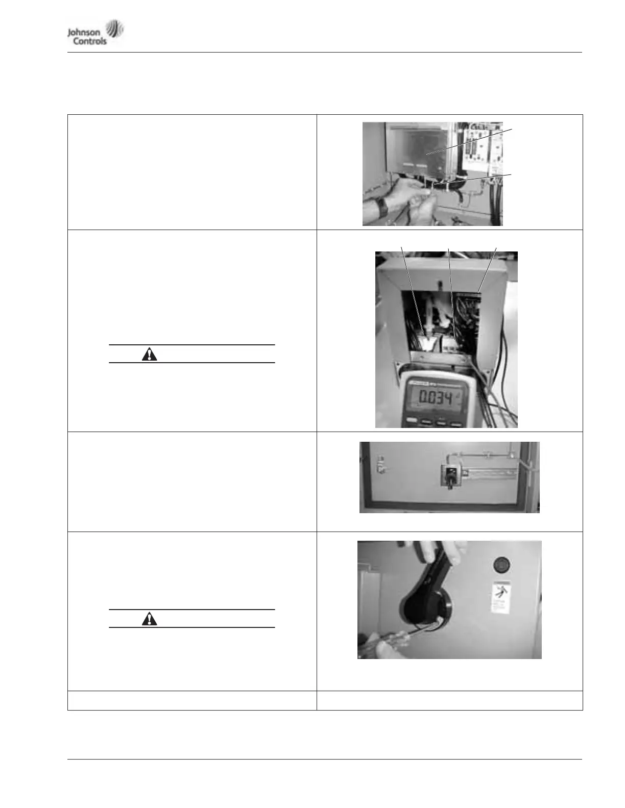
Static Check
23. Use a Phillips screwdriver to remove all the faceplate
screws on the high-voltage faceplate, and remove the
faceplate.
Note: Location of the screws may vary from the drive
illustrated. There may be screws securing a bottom faceplate,
which also need to be removed.
Static Check
24. Make sure power is off, and perform static checks as
described in Table 5-10 (for the converter), Table 5-11
(for the inverter) and Table 5-12 (for the DC bus). Refer to
Page 5-14.
Note: Static check shown is for L3 and B+ terminals.
25. Once the pre-power static checks are completed,
reinstall the drive’s outer and side covers, tightening
all the screws.
High Voltage is present on L1, L2, L3, B-, B+, BT, T1, T2, T3.
Starting Drive
26. Make sure that the drive’s 3rd contactor S1 switch, if
present, is in the ON position (shown in OFF position).
Note: The bypass mode operates with the switch in the OFF
position, however the drive will not run. Yet the keypad
will operate.
27. Reinsert the keypad cable and control board on
small drives.
Starting Drive
28. Close the drive door, and turn the circuit breaker handle in
a clockwise direction.
29. Go to Appendix E for keypad operation.
Note: If the circuit breaker latch is locked, use a flat-blade
screwdriver to turn the screw to release the handle.
High Voltage
● Always work with another person.
● Be sure equipment is properly grounded.
● Wear safety glasses.
Start-Up Wizard
See Page 7-4, Start-Up Wizard
High-Voltage
Faceplate
Optional Bottom
Faceplate
WARNING
L1, L2, L3 B-, B+, BT T1, T2, T3
WARNING