3
3 – 58
3.3
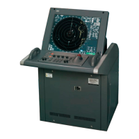
PM pattern
16〜18NM
P. MON 6.0
An example of the display of PM pattern
Check of the transmission system
The value of [P. MON] displayed in the lower right corner of the screen represents the transmission power.
If the current values is extremely smaller than the value recorded during the initial check, the transmission
system requires inspection by a service engineer.
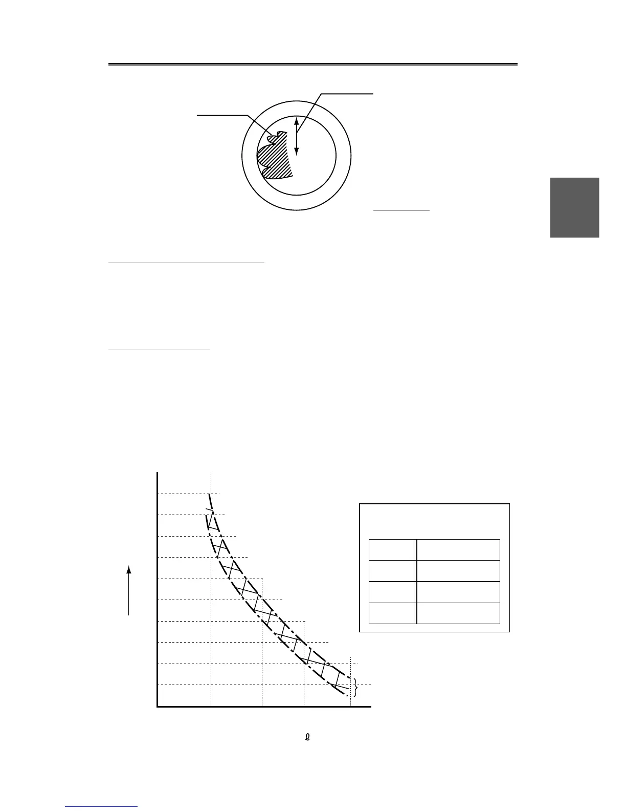
Checking procedures:
q Read the current value.
w Using calibration curve I, obtain the value of relative attenuation d(B) corresponding to the initial
value B recorded on the Information Label.
e Using calibration curve I, obtain the value of relative attenuation d(A) corresponding to A, then d(A)
- d(B) represents the attenuation of the current transmission poser as compared with the initial state.
r When the attenuation expresses by d(A) - d(B) has exceeded 10 dB (due to the life of the magnetron),
the transmission system requires inspection by a service engineer.
Calibration Curve I
Bar indication bar length
22
20
18
16
14
12
10
8
6
4
2
0
dB
Relative attenuation value d
The
measurement
precision
012 453678109
PERF. MONITOR
INFORMATION LABEL
DATE P. MON
 Loading...