8-20
8 8 8
8.5 Replacement of Major Parts
yyyy
yyyy
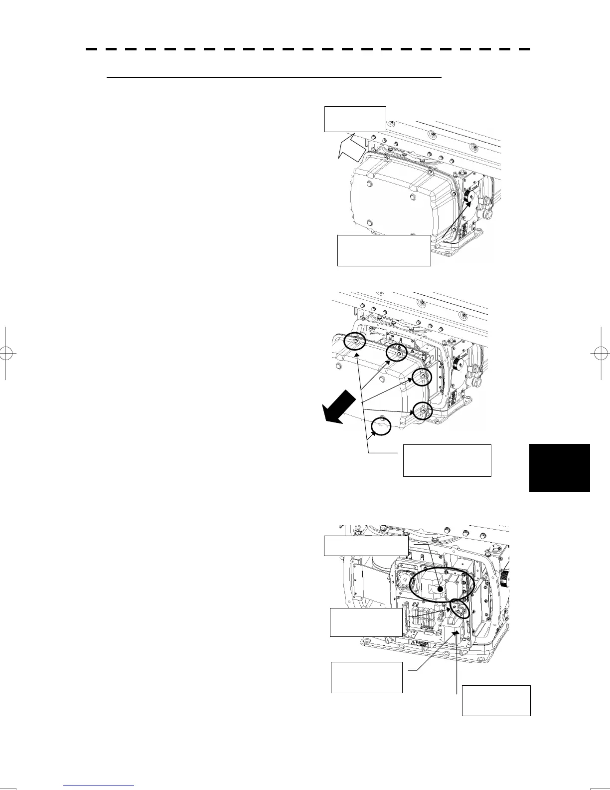
Magnetron Replacement Procedure for Scanner Unit NKE-1130
(1) Before starting part replacement work,
turn off the safety switch of the scanner
unit.
The safety switch is located on the rear (stern) side.
Remove the cover and turn off (to the lower side)
the safety switch.
(2) Remove the pedestal cover.
Remove the cover on the left (port) side.
(3) Check that there is no remaining
electric charge in the modulation
high-voltage circuit board.
Remove the two screws (M4) holding the
magnetron cables (both yellow and green).
Remove the eight
hexagonal screws.
Removing the port side cover
Bow side
Turn off the safety
switch.
Magnetron
Remove the
yellow cable.
Remove the
green cable.
Remove the
two screws.

 Loading...


