EasyManuals Logo

JRC JMA-932B-SA User Manual

JRC JMA-932B-SA
486 pages
To Next Page IconTo Next Page
To Previous Page IconTo Previous Page
Page #456 background imageLoading...
Page #456 background image
B-7
Line Filter
Line Filter
Circuit
Breker
Input Select
Line Filter
Relay
Circuit
Relay
Circuit
250V CNT
Power
Control
Circuit
AC-DC
P+5V
+48V
P+12V
+12V
+5V
Ship's Main
AC100-115V
AC220-240V
50/60Hz, 1φ
LCD Power
AC100-115V
AC220-240V
50/60Hz, 1φ
Scanner Moter
AC100-115V
AC220-240V
50/60Hz, 1φ
Inverter
Power
Control
Circuit
Inverter
CBD-1851
UPS Battery
+5VAR
+12V
+5V
+3.3V
-12V
-5V
10A
1.5A
0.3A
0.8A
14A
21A
TXRX(MTR)
Power
3.5A
1A
150mA
10A
2A
Battery
DC24V
Hi Voltage Save Circuit
CBD-1832
Power Supply Unit
CBD-1625
ATX Power Supply
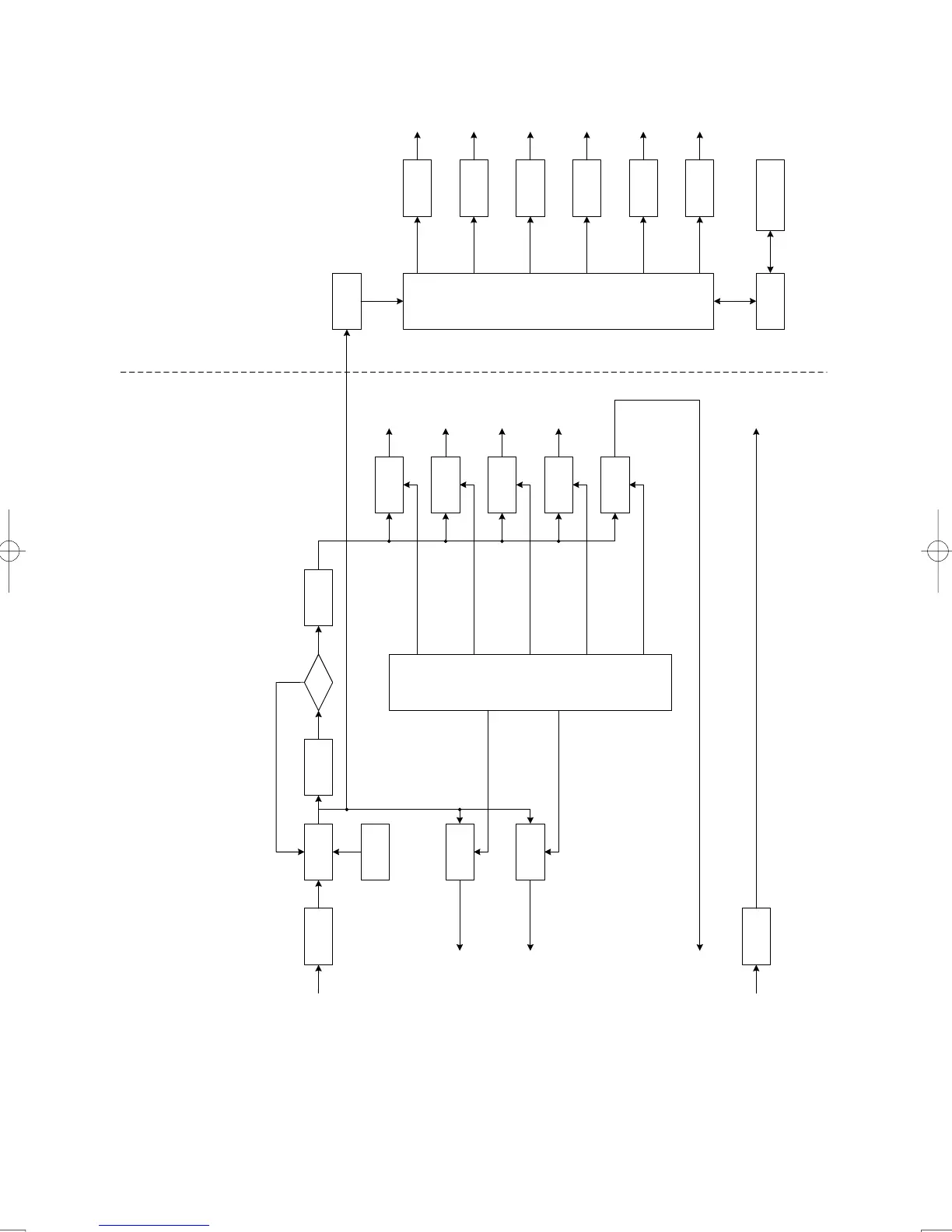
Fig B-107. Primary Power Supply System Block Diagram

Table of Contents

Questions and Answers:

Question and Answer IconNeed help?

Do you have a question about the JRC JMA-932B-SA and is the answer not in the manual?

JRC JMA-932B-SA Specifications

General IconGeneral
BrandJRC
ModelJMA-932B-SA
CategoryMarine Radar
LanguageEnglish

Related product manuals