1-28
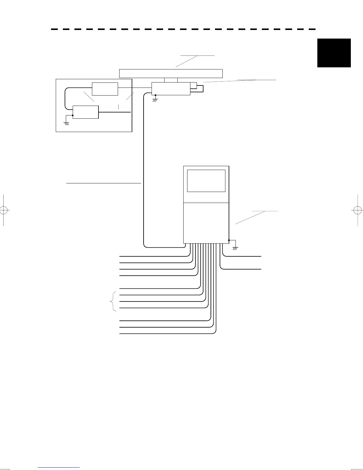
1.5 General System Diagrams
y
1
NCD-2096
DISPLAY UNIT
NJU-85
PERFORMANCE
MONITOR
250V-MPYCYS-7
250V-TTYCS-1
KB-CHD152K
250V-TTYCS-1
18 CORES COMPOSITE CABLE
H-2695111153
MAX 18.0φ (JRC SUPPLY)
250V-TTYCS-4
H-2695110006 (JRC SUPPLY)
H-2668510019 (JRC SUPPLY) SPARE
250V-MPYC-4
250V-TTYCS-4
250V-TTYCS-4
GYRO
LOG
(NMEA 0183)
DGPS
VDR
RADAR
(INTER SWITCH)
ECDIS(JAN-901M)
ALERM MONITORING SYSTEM
(NEAREST APPROACH)
(POWER FAIL)
CONNING DISPLAY(JAN-701-CON)
AIS
0.6/1kV-DPYCY-6
0.6/1kV-DPYCYS-1.5
SHIP’S MAIN
AC100/220V,
50/60Hz,1φ,800VA
SHIP’S MAIN
for POWER FAIL ALARM
DC24V(BATTERY),1W
(5A)
NBL-175
SHIP’S MAIN
for HEATER
AC220V,50/60Hz,1φ
AC100V,50/60Hz
1φ,100W
CIRCUIT BREAKER
(SHIP YARD SUPPLY)
(WITH MON)
NKE-1125-9
SCANNER UNIT
14 CORES COMPOSITE CABLE
H-2695110056
MAX 23φ (JRC SUPPLY)
65m MAX
STEPDOWN
TRANSFORMER
0.6/1kV-DPYCYS-1.5
HEATER OPTION
Note: Eliminating the interference on frequencies used for marine communications and navigation
due to operation of the radar.
All cables of the radar are to be run away from the cables of radio equipment.
(Ex. Radiotelephone. Communications receiver and direction finder, etc. )
Especially inter-wiring cables between scanner unit and display unit of the radar should not be
run parallel with the cables of radio equipment.
Fig. 1.21 General System Diagram of Radar, Type JMA-922B-9XA