Do you have a question about the JUMO mTRON T and is the answer not in the manual?
Lists available documents for the system, including data sheets and manuals.
Details important safety warnings, symbols, and precautions for handling and installation.
Provides an overview of the multifunction panel 840's capabilities and features.
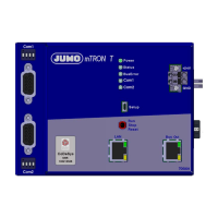
Identifies and describes all physical connection ports on the device.
Covers site requirements, climatic conditions, DIN rail mounting, and space considerations.
Step-by-step instructions for physically installing the panel into a cutout.
Essential guidelines for personnel, cable handling, shielding, grounding, and electrical safety.
Illustrates the physical layout and labeling of all electrical connection points.
Explains the user interface, touch control, and general screen layout.
Details how to display and interpret analog and digital signals in a graphical diagram format.
Describes how to view and manage counter and integrator statuses.
Explains how to use the memory display function for checking recorded data.
Details the process for acknowledging alarms received from the base unit.
Shows the current status of all connected modules and error reporting.
Provides a log of user interventions and system events.
Covers the configuration of PLC parameters for the central processing unit.
Covers parameters that can be edited for the Human-Machine Interface.
Explains how to select signals for configuration from available analog and digital inputs.
Defines general device settings like name, memory, and data download options.
Details how to configure analog input channels, including range and alarm settings.
Covers the setup and configuration of channel groups for data recording.
Details the configuration of batches for controlling processes and saving batch reports.
Describes the settings for Modbus/TCP communication and network configuration.
Covers configuration for RS232/RS422/485 interfaces and Modbus RTU operation.
Allows selection and configuration of parameters for user-specific views.
Covers creating and customizing graphical process screens for visualization.
Configures network settings (IP address, subnet mask) for LAN communication.
Details the process for releasing or blocking additional panel functions.
Guides setting the system date and time, or synchronizing with a PC.
Guides through testing display colors and calibrating the touchscreen.
Provides detailed specifications for interfaces, screen, and electrical data.
Provides information on barcode scanner initialization and batch control barcodes.
| Category | Control Systems |
|---|---|
| Power Supply | 24 V DC |
| Output Types | Relay, Analog, Digital |
| Communication Interfaces | Ethernet |
| Main processor | ARM Cortex-M |