199
13 Configuration
13.18.4 Digital signals (overview)
The following table contains all digital signals that are available for connecting to the digital in-
puts of the multifunction panel and for controlling batch reporting.
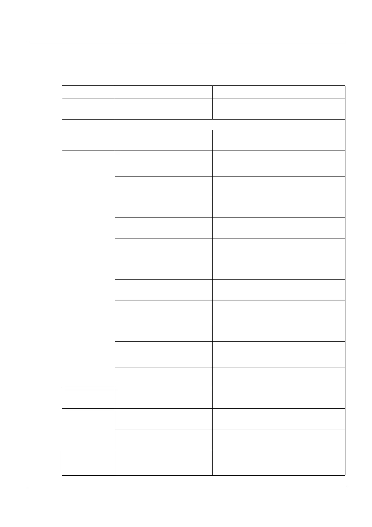
Category Signal Description
Inactive No signal selected
Central processing unit
Digital variables Digital variable 1 to 64 Digital variable 1 to 64 (via interface)
Program
generator 1 to
Program
generator 9
Operating contact 1 to 16 Operating contact 1 to 16 of program channels
(in the three program channels, operating con-
tacts with the same name are linked with OR)
Mode: Basic status Status: Program is not running (basic status)
Mode: Automatic Status: Program is running (automatic mode,
no delay time or program end time)
Mode: Automatic 1 Status: Program is running (automatic mode,
incl. delay time and program end time)
Mode: Standstill Status: Program stopped during automatic
mode (time base stopped)
Mode: Delay Status: Program start delayed (delay time
runs)
Mode: Program end Status: Program ends (program end time runs,
corresponds to length of end signal)
Mode: Manual Status: Manual mode
Tolerance band channel 1 to 3 Tolerance band signal of program channel 1 to
3
Batch control Signal to control the batch recording (OR-
linked signals "Automatic", "Standstill", and
"Program end").
PLC Binary output 28 to 32 Signal of PLC digital output 28 to 32
Limit monitoring Limit monitoring 1 to 64 Output signal of limit value monitoring 1 to 64
Binary linking Binary linking 1 to 8 Result of binary linking 1 to 8
PLC Binary output 9 to 32 Signal of PLC digital output 9 to 32
Binary PLC out-
put block 13 to
block 18
PLC Binary output 1 to 32 Signal of PLC digital output 1 to 32