39
4 Electrical connection
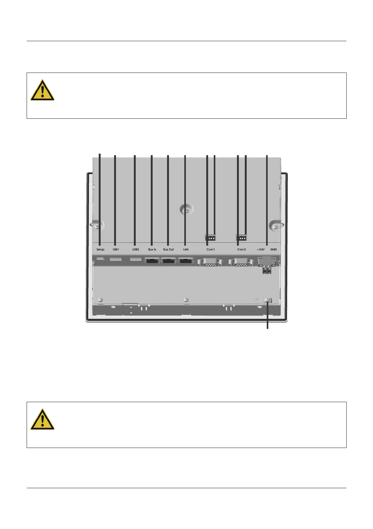
4.3 Connection diagram
4.3.1 Connection elements
CAUTION!
At maximum load, the temperature at the "+24 V" and "GND" terminals (Voltage supply In)
may exceed 60 °C.
As a result the insulation of the cable may be damaged.
The cable must be heat resistant up to at least 80 °C.
(1) (2)
(3)
(4)
(5)
(6)
(7)
(8)
(9)
(10)
(11)
(12)
(1) USB device interface (setup) (2) USB host interface 1
(3) USB host interface 2 (4) System bus In
(5) System bus Out (6) LAN interface
(7) Com1 interface (8) Com1 terminating resistor
(9) Com2 interface (10) Com2 terminating resistor
(11) Voltage supply In, DC 24 V (12) Functional grounding
CAUTION!
Functional grounding:
Connection terminal for functional ground.
To meet the specified EMC characteristics, this terminal must be connected to functional
ground.