197
13 Configuration
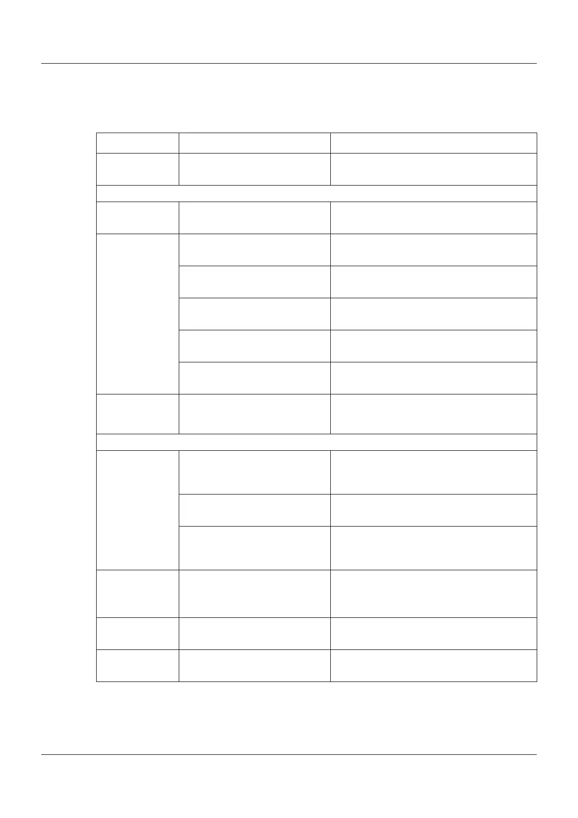
13.18.3 Analog signals (overview)
The following table contains all analog signals that are available for connecting to the analog
inputs of the multifunction panel.
Category Signal Description
Inactive No signal selected
Central processing unit
Analog variables Analog variable 1 to 64 Analog variable 1 to 64 (via interface)
Program
generator 1 to
Program
generator 9
Channel 1 SP1 to Channel 3 SP1 Setpoint value 1 of program channel 1 to 3
Channel 1 SP2 to Channel 3 SP2 Setpoint value 2 of program channel 1 to 3
Channel 1 SP2 to Channel 3 SP2 Setpoint value 3 of program channel 1 to 3
Channel 1 SP4 to Channel 3 SP4 Setpoint value 4 of program channel 1 to 3
PLC Analog output 13 to 16 Signal of PLC analog output 13 to 16
Analog PLC out-
put block 10 to
block 18
PLC Analog output 1 to 16 Signal of PLC analog output 1 to 16
Multichannel controller module
Controller C01ActualValue to
C04ActualValue
Actual value of controller channel 1 to 4
C01Setpoint to C04Setpoint Setpoint value of controller channel 1 to 4
C01OutpLevelMon to
C04OutpLevelMon
Output level (display value) of controller
module 1 to 4
Analog inputs AI01 to AI04 Measured value of analog input 1 to 4
Mathematics Math01 to Math04 Result of math function 1 to 4
HW counter HWCounter Counter reading of hardware counter